Fuel gas mixing bag for producting energy saving lamp

An energy-saving lamp and gas technology, which is applied in the manufacture of ships or lead wires, etc., can solve the problems of scattered adjustment switches, easy formation of turbulent and eddy current dead angles, inconvenient operation, etc. The effect of the overall layout

Active Publication Date: 2011-10-05
佛山市南海高拓包装材料有限公司
View PDF0 Cites 0 Cited by
  • Summary
  • Abstract
  • Description
  • Claims
  • Application Information

AI Technical Summary

Problems solved by technology

[0003] 1. When there are many fire points and a large amount of fire, in order to facilitate the welding of branch pipes, the main pipe with large diameter is often very long
[0004] 2. Each fire point corresponds to multiple pipe circumferential welds and multiple threaded connections, resulting in many hidden failure points, high maintenance rate and inconvenient processing
[0005] 3. When other production factors such as air pressure fluctuations change, it is necessary to adjust the height and temperature of the flame, because the adjustment switches are scattered, which is not conducive to rapid adjustment
[0006] 4. The gas mixing effect of this method is not good, which affects the flame energy efficiency and shape stability, and easily forms turbulent flow and eddy current dead angle, resulting in unstable product quality and affecting production efficiency
[0007] 5. The overall layout is messy and inconvenient to operate
[0008] 6. When checking the gas circuit of the machine, the whole machine must be completely shut down before proceeding.
[0009] 7. It is easy to produce toxic and harmful flammable gases

Method used


Image

  • Fuel gas mixing bag for producting energy saving lamp
  • Fuel gas mixing bag for producting energy saving lamp
  • Fuel gas mixing bag for producting energy saving lamp

Examples


Embodiment Construction

[0023] The present invention will be described with reference to the drawings and embodiments:

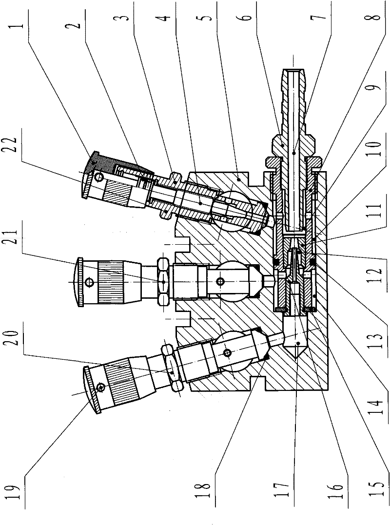
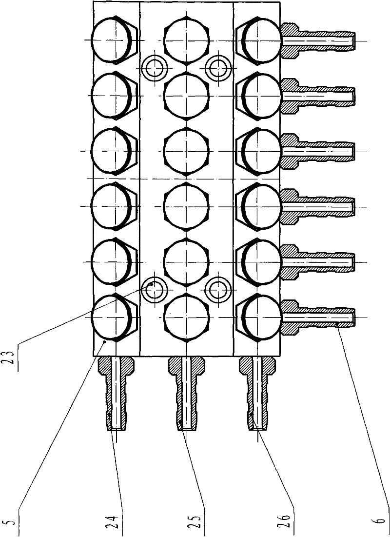
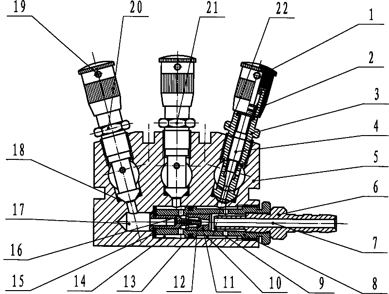
[0024] Such as figure 1 , figure 2 As shown, a gas mixing bag for the production of energy-saving lamps is mainly composed of a valve body 5, a regulating valve, and a gas mixing valve. The valve body 5 is provided with three independent main cavities. The independent main pipe cavity is connected to the oxygen source, compressed air source, and fuel gas source through the oxygen connector 24, compressed air connector 25, and gas connector 26 to form an independent oxygen main line, compressed air main line, and gas main line; There is a row of adjustment valves corresponding to the oxygen main line, compressed air main line, and gas main line. Each row of adjustment valves is an oxygen adjustment valve 20, a compressed air adjustment valve 21, and a gas adjustment valve 22; the oxygen adjustment valve 20, compression The air adjusting valve 21 and the gas adjusting valve 22 are all...


PUM


Abstract

The invention belongs to the technical field of energy-saving light production equipment and mainly relates to a fuel gas mixing bag, which mainly comprises a valve body (5), a regulating valve and a gas mixing valve, wherein three independent main pipe cavities are formed in the valve (5), and are connected with an oxygen source, a compressed air source and a fuel gas source to form an oxygen main pipe, a compressed air main pipe and a fuel gas main pipe, which are independent; correspondingly, each of the oxygen main pipe, the compressed air main pipe, the fuel gas main pipe is provided with a row of regulating valves; each three regulating valves which are communicated with the three main pipes respectively form a group and are communicated with a corresponding gas mixing valve; and each gas mixing valve is connected with a fire using point by a mixed gas connector (6) and a pipe. In the invention, the independent valve structure simplifies overall arrangement and shortens the lengths of the main pipes; and the regulating valves arranged in a concentrated manner can perform concentrated control and realization of the mixing of gases in any ratio; and the fuel gas mixing bag has the characteristics of convenient operation and maintenance and convenient installation.

Description

Technical field [0001] The invention belongs to the technical field of energy-saving lamp production equipment, and mainly relates to a gas mixing bag used for the production of energy-saving lamps. Background technique [0002] At present, the flame adjustment method used in the production process of the energy-saving lamp tube is a separate control method, that is, the three gases used for each fire point are connected to the branch pipes from the three gas source main pipes, and each gas passes through the valve. After adjusting the gas output, it is sent to the burner through the gas mixing pipe. There are mainly the following problems when using this method: [0003] 1. When there are many fire points and a large amount of fire, in order to facilitate the welding of branch pipes, the main pipe with large diameter is often very long. [0004] 2. There will be multiple pipe circumferential welds corresponding to each fire point, and multiple threaded connections, resulting in ma...

Claims


Application Information

Patent Timeline
Patent Type & Authority Patents(China)
IPC IPC(8): H01J9/24
Inventor 李华文袁伟强
Owner 佛山市南海高拓包装材料有限公司
Why Eureka
Try Eureka