Calculation method and device for wavelength allocation

A wavelength allocation and calculation method technology, which is applied in wavelength division multiplexing systems, electrical components, optical multiplexing systems, etc., can solve the problems of low wavelength allocation calculation efficiency, increased complexity of routing path topology, and wavelength allocation complexity. increase and other issues, to achieve the effect of simple implementation, simple calculation principle, and reduced calculation time

Active Publication Date: 2010-09-15
ZTE CORP
View PDF5 Cites 6 Cited by
  • Summary
  • Abstract
  • Description
  • Claims
  • Application Information

AI Technical Summary

Problems solved by technology

At present, the RWA algorithm is mainly implemented through the wavelength graph layering algorithm. The wavelength graph layering algorithm is mainly as follows: each wavelength is abstracted into a node, and the wavelength assignment is realized by selecting the link between the abstracted node and the original node, namely: Abstracting each wavelength into a node is equivalent to adding multiple nodes on the basis of the original number of nodes. The number of nodes added is the same as the total number of all wavelengths. Correspondi

Method used


Image

  • Calculation method and device for wavelength allocation
  • Calculation method and device for wavelength allocation
  • Calculation method and device for wavelength allocation

Examples


Embodiment 1

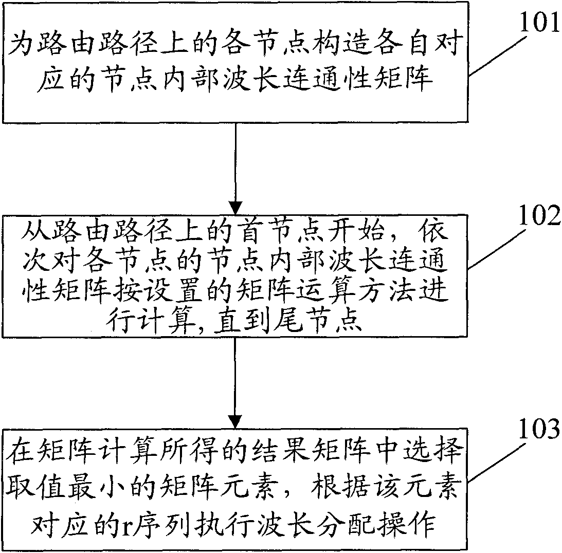
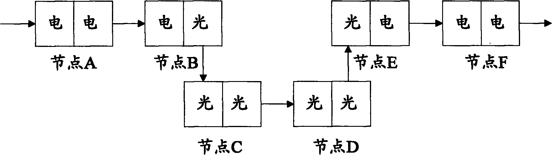
[0068] There are six nodes on the routing path in this embodiment, such as figure 2 As shown, node A, node B, node C, node D, node E and node F are respectively, node A is the first node, which is an electrical and electrical node; node B is an electrical and optical node; node C is an optical-optical node; node D is an optical node Optical node; node E is an optoelectronic node; node F is a tail node, which is an electrical and electrical node.

[0069] The internal wavelength connectivity matrices constructed for node A to node F are: 1*1-order matrix A, 1*n-order matrix B, n*n-order matrix C, n*n-order matrix D, and n*1-order matrix E and 1*1 order matrix F, and then start the matrix operation from node A as follows:

[0070] Perform Δ operation on matrix A(1*1) and matrix B(1*n), set the operation result as matrix B1(1*n), and record the r corresponding to B1(1*n);

[0071] Perform Δ operation on matrix B1(1*n) and matrix C(n*n), set the operation result as matrix C1(1*...

Embodiment 2

[0077] There are only two nodes on the routing path in this embodiment, and let them be respectively figure 2 The node C and node D in the node C is the first node, which is the optical node; the node D is the tail node, which is also the optical node.

[0078] The intra-node wavelength connectivity matrices constructed for node C and node D are respectively: n*n-order matrix C and n*n-order matrix D, and then the matrix operation from node C is performed as follows:

[0079] Perform Δ operation on matrix C(n*n) and matrix D(n*n), set the operation result as matrix D1(n*n), and record the r corresponding to D1(n*n);

[0080] After the above calculation process, the matrix D1(n*n) reflects the wavelength connectivity from the ingress port of the head node C to the egress port of the tail node D. Select the non-∞ element d with the smallest value from the matrix operation result matrix D1 ij , using the recorded and d ij The corresponding r sequence performs wavelength assign...


PUM


Abstract

The invention discloses a calculation method for wavelength allocation, which comprises the steps of: constructing internal node wavelength connectivity matrixes corresponding to nodes for the nodes on a route path; and calculating the internal node wavelength connectivity matrix of each node by a set matrix operation method from the initial node on the route path till the tail node on the route path. The invention also discloses a calculation device for wavelength allocation. The method and the device can be used to shorten the time on the calculation of wavelength allocation.

Description

technical field [0001] The present invention relates to wavelength allocation technology in the technical field of optical communication, and in particular, to a calculation method and device for wavelength allocation. Background technique [0002] Among the current optical layer networking technologies, the most commonly used is Dense Wavelength Multiplexing (DWDM) technology. DWDM technology can multiplex multiple wavelengths into one optical fiber to increase the bandwidth of the existing optical fiber backbone network. The traditional DWDM system is essentially a point-to-point line system. Most of the optical layer networking can only realize the construction of the optical layer line system through the terminal station (TM), and then the optical add-drop multiplexer (OADM) appears. ) gradually realize the development from point-to-point networking to ring network. However, OADM can only add one or more fixed number of wavelengths, and the routing of nodes is determine...

Claims


Application Information

Patent Timeline
IPC IPC(8): H04J14/02
CPCH04J14/0267H04J14/0257H04J14/0269H04J14/0227
Inventor 汪文颖王家昱
Owner ZTE CORP
Why Eureka
Try Eureka