Injection device of cold-chamber die casting machine

A cold-chamber die-casting and pressure technology, applied in the field of cold-chamber die-casting machine injection devices, can solve the problems of insufficient speed of injection, unqualified die-casting products, poor fluidity, etc., so as to shorten the construction time and save energy. The cost of machining, the effect of simplifying the hydraulic system

Inactive Publication Date: 2012-01-11
卢志刚
View PDF0 Cites 0 Cited by
  • Summary
  • Abstract
  • Description
  • Claims
  • Application Information

AI Technical Summary

Problems solved by technology

[0002] A good cold-chamber die-casting machine must have high injection performance, so that it can be used in a wider range and the pass rate of die-casting products is higher; while the injection system of most existing domestic cold-chamber die-casting machines , in the application field that requires high-speed die-casting, it cannot show high performance. Its shortcomings are mainly as follows: 1. The injection speed is not fast enough. For many die-casting products, due to its short rapid injection stroke, Often the injection has ended, but the injection speed has not risen to the maximum speed it can reach. When the metal liquid fills the mold cavity, the temperature rises too slowly and the fluidity becomes poor. Fill the mold cavity well, or make the surface of the die-casting product not meet the due requirements
2. If the pressure build-up time is too long, it will cause the metal material liquid in the mold cavity to cool down too much when the boost pressure is in place, the fluidity is already very poor, the boost pressure has no effect, and the die-casting products produced Density is not good enough, die casting products are unqualified

Method used


Image

  • Injection device of cold-chamber die casting machine
  • Injection device of cold-chamber die casting machine
  • Injection device of cold-chamber die casting machine

Examples


Embodiment Construction

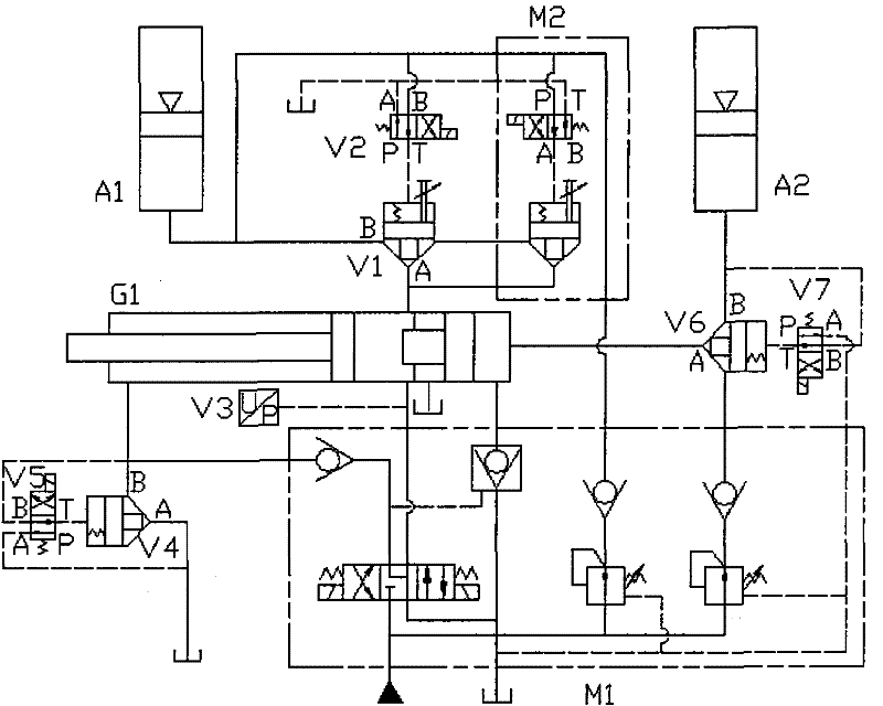
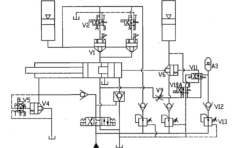
[0012] The patent of the present invention will be described in detail below in conjunction with the above-mentioned drawings. This embodiment takes the standard configuration of a domestic cold chamber die-casting machine 800T as an example, and its hydraulic principle is as attached figure 1 shown.

[0013] When the injection system changes from slow speed to fast injection, the directional valves V2 and V5 are energized, the oil in the spring chamber of the cartridge valve V1 drains oil through the T port of V2 to the A port, the cartridge valve V2 is opened, and the accumulator passes through The cartridge valve V1 quickly fills the rodless chamber of the injection cylinder with oil, and at the same time, the oil in the spring chamber of the cartridge valve V4 drains oil to the A port through the T port of V5, and the cartridge valve V4 opens to realize rapid injection. But in this process, in the originally designed hydraulic system, the directional valve V2 drains oil fr...


PUM


Abstract

The invention discloses a filling device of a cold-chamber die casting machine composed of direction valves V2, V5 and V7 and cartridge valves V1, V4 and V6 as well as a pressure sensor V3, wherein a spring chamber of the cartridge valve V1 is connected to a T port or a P port of the direction valve V2, the spring chamber of the cartridge valve V4 is connected to the T port or P port of the direction valve V5, the spring chamber of the cartridge valve V6 is connected to the T port or P port of the direction valve V7; when the direction valves are electrified to control the starting of the cartridge valves, an oil flowing direction of the spring chamber of the cartridge valves is in accordance with the thrust direction of an electromagnet, so that the oil passing capacity of the direction valves reaches the highest level, and can more rapidly open the cartridge valves, thereby quickening the time from a slow speed to a rapid speed during a filling process, shortening a pressure building time for increasing pressure and filling, and improving key performances of the cold-chamber die casting machine in the filling system. The invention has good effect for the die casting product requiring high speed and short injection time, such as magnesium alloy die castings, thin-walled die castings, die-castings of complex shapes and the like.

Description

technical field [0001] The patent of the present invention relates to a cold chamber die-casting machine injection device, especially a cold chamber die-casting machine injection device that requires high-speed injection, rapid pressure build-up, and rapid injection and pressurized injection in a short period of time. Background technique [0002] A good cold chamber die-casting machine must have high injection performance, so that it can be used in a wider range and the qualified rate of die-casting products is higher; while the injection system of most existing domestic cold chamber die-casting machines , in the application field that requires high-speed die-casting, it cannot show high performance. Its shortcomings are mainly as follows: 1. The injection speed is not fast enough. For many die-casting products, due to its short rapid injection stroke, Often the injection has ended, but the injection speed has not risen to the maximum speed it can reach. When the metal liqu...

Claims


Application Information

Patent Timeline
Patent Type & Authority Patents(China)
IPC IPC(8): B22D17/08B22D17/30
Inventor 卢志刚
Owner 卢志刚
Why Eureka
Try Eureka