
Fluid catalytic conversion feeding preheating and reaction temperature control method

A technology of reaction temperature and fluidized catalysis, which is applied in catalytic cracking, chemical instruments and methods, and hydrocarbon production from oxygen-containing organic compounds, etc., can solve problems affecting reaction selectivity and conversion rate, unfavorable yield of light fractions, etc., to achieve The effect of flexible adjustment of reaction temperature, high energy utilization efficiency, and improvement of energy recovery rate and utilization efficiency

Active Publication Date: 2010-09-22
李群柱
View PDF0 Cites 4 Cited by
  • Summary
  • Abstract
  • Description
  • Claims
  • Application Information

AI Technical Summary

Problems solved by technology

In this way, controlling the reaction temperature of the riser by adjusting the amount of catalyst circulation will inevitably affect the number of catalyst active centers in the reactor, thereby affecting the selectivity and conversion rate of the reaction, which is unfavorable for improving product distribution and increasing the yield of light fractions.

Method used


Image

  • Fluid catalytic conversion feeding preheating and reaction temperature control method
  • Fluid catalytic conversion feeding preheating and reaction temperature control method

Examples


example 1

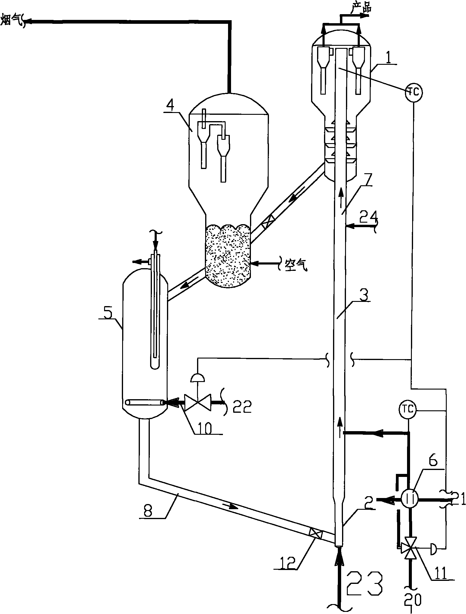
[0035] as attached figure 1 Shown: the catalytic conversion device adopting the method for feed preheating and reaction temperature control of the present invention includes a settler 1, and the riser reactor includes a pre-lift zone 2, a riser first reaction zone 3, and a second reaction zone 7 , regenerator 4, regenerated catalyst delivery pipe 8 (comprising control valve 12), regenerated catalyst cooler 5 and fluidized medium flow control valve 10 (for regulating the fluidized medium flow rate of regenerated catalyst cooler and then regulating the temperature of cold regenerated catalyst ), raw oil heater 6 and control valve 11 (for adjusting the bypass flow of raw oil and then adjusting the preheating temperature of raw oil).

[0036]The preheated heavy oil raw material 20 has a temperature of about 200-230°C. After being heated by the raw oil heater 6 of the present invention with the heating medium 21, it is mixed with the cold regenerated catalyst lifted and transported...

example 2

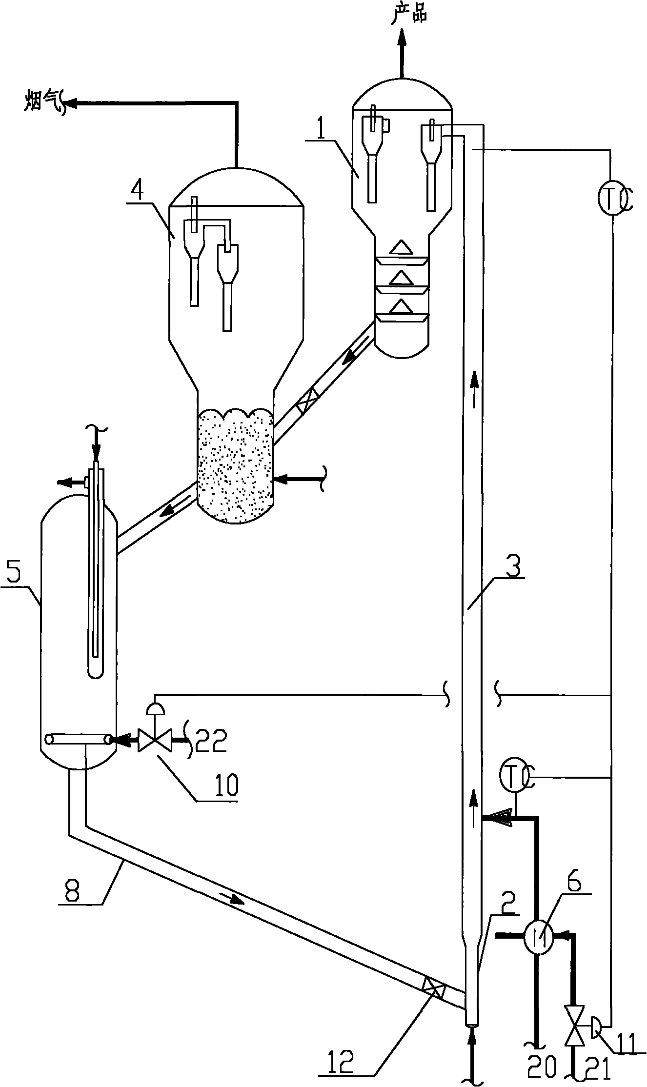
[0041] as attached figure 2 Shown: adopt the catalytic conversion device of the method for feed preheating and reaction temperature control of the present invention, comprise settler 1, riser reactor comprises pre-lift zone 2, riser reaction zone 3, regenerator 4, regenerated catalyst conveys Pipe 8 (including control valve 12), regenerated catalyst cooler 5 and fluidized medium flow control valve 10 (used to adjust the fluidized medium flow rate of regenerated catalyst cooler and then adjust the temperature of cold regenerated catalyst), raw oil heater 6 and Control valve 11 (for adjusting the bypass flow rate of heating medium 21 and then adjusting the preheating temperature of raw oil).

[0042] Unpreheated light hydrocarbon raw material (gasoline) 20 with a temperature of about 40° C., after being heated by the heating medium 21 of the feed oil heater 6 of the present invention, is mixed with the cold regenerated catalyst and enters the reaction zone 3 of the light hydroc...


PUM


Abstract

The invention provides a petroleum fluid catalytic conversion control method. After being heated, raw oil enters a reactor and carries out catalytic conversion reaction after being mixed with recyclable catalyst which enters the reactor. The method is characterized in that the preheating temperature of the raw oil needs to be regulated when controlling the reaction temperature of the reactor. The control method overcomes the defects in the prior art, enhances the selectivity and the conversion rate of the fluid catalytic conversion reaction, improves the product distribution, enhances the yield of light distillate and has the characteristics of having reliable running and flexible regulation and saving energy and investment.

Description

technical field [0001] The invention belongs to the field of petroleum refining, and in particular relates to the control technology of feed preheating and reaction temperature for catalytic conversion of hydrocarbon raw materials. Background technique [0002] Fluid catalytic cracking is one of the most important petrochemical processing processes, the purpose is to produce high-quality gasoline and liquefied petroleum gas as petrochemical raw materials from heavy oil. In the catalytic cracking unit, hydrocarbon feedstock undergoes gas-solid phase cracking reaction in the presence of a catalyst, and the high-temperature catalyst enters the catalytic cracking unit to play a catalytic role after being regenerated. The riser reactor is the core equipment of the catalytic cracking unit. The existing riser reactor includes a pre-lift section and a reaction section. The regenerated catalyst enters the pre-lift section from the catalyst inlet, and enters the reaction section to pl...

Claims


Application Information

Patent Timeline
IPC IPC(8): C10G11/18B01J8/24C07C11/04C07C1/24
CPCY02P20/52Y02P20/584Y02P30/20Y02P30/40
Inventor 李群柱李莉
Owner 李群柱
Learn More