

Ultrasonic barrel plating technique and device thereof
A kind of equipment, ultrasonic technology, applied in the electrolysis process, electrolysis components, etc., can solve the problem that the ultrasonic vibration function cannot be attached to the barrel plating tank, etc.
- Summary
- Abstract
- Description
- Claims
- Application Information
AI Technical Summary
Problems solved by technology
Method used
Image

Examples
Embodiment 1
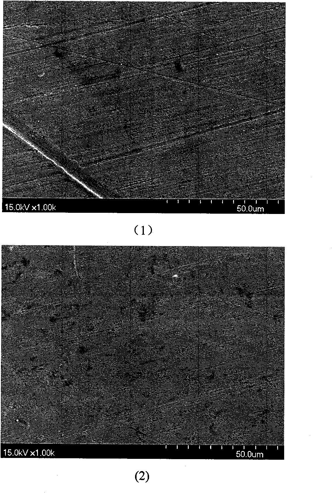
[0016] Nickel plating on sintered NdFeB magnets to prevent corrosion of NdFeB magnets, the process conditions used are: NiSO 4 .7H 2 O 250 g / L, NiCl 2 .6H 2 O 50 g / L, H 3 BO 3 40 g / L, sodium lauryl sulfate 0.06 g / L, adjust the pH of the electroplating solution to 3.5, raise the temperature of the plating solution to 40°C, and the cathode current density is 1 ampere / square decimeter; start the ultrasonic generation before the electroplating starts Dispersed by means of an ultrasonic wave with an ultrasonic frequency of 25KHz and an ultrasonic power intensity of 0.5 watts / square centimeter, the microstructure of the obtained coating is as attached image 3 As shown in (1), using the same electroplating process, the microstructure of the coating obtained when the ultrasonic generator is not turned on is shown in the attached image 3 (2) shown. It can be seen from the figure that the coating layer is obviously much denser using the barrel plating equipment with ultrasonic w...
Embodiment 2
[0018] Copper plating on stainless steel with deep holes, the depth of the hole is 100mm, the diameter is 1mm, using ultrasonic barrel plating equipment, the electroplating solution is CuSO 4 ·5H 2 O 40 g / l; K 2 CO 3 80 g / L; HEDP 80 g / L; use KOH to adjust pH=9.5 temperature: 30°C, cathode current density: 1 ampere / square decimeter, anode-to-cathode area ratio greater than 2, start the ultrasonic generator before electroplating starts, The ultrasonic frequency is 30KHz, and the ultrasonic power intensity is 0.5 watts / square centimeter. After the electroplating is completed, it is found that the deep plating of the deep hole electroplating can reach 70mm. Turn off the ultrasonic generator, and conduct a comparative experiment under the same electroplating conditions. The result is that the coating depth obtained is only 20mm. . This shows that under the condition of using the ultrasonic generator, the coating performance of the inner wall of the deep hole can be greatly impro...
PUM
 Abstract
Description
Claims
Application Information