

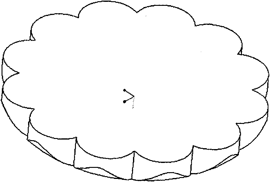
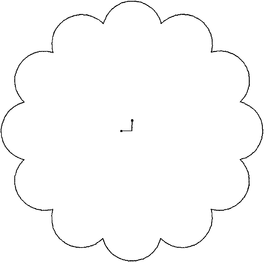
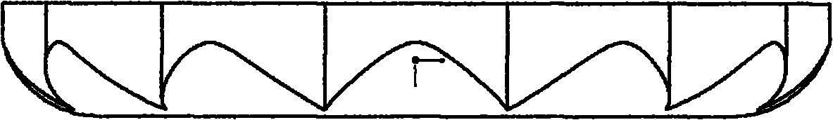
Lateral-swirl combustion chamber
A combustion chamber and plume technology, applied to combustion engines, internal combustion piston engines, machines/engines, etc., can solve problems such as inability to make full use of air, increase power, and less fuel arrival, and achieve cutting-edge shunt modeling. The effect of reducing the requirement of intake vortex and improving air utilization
- Summary
- Abstract
- Description
- Claims
- Application Information
AI Technical Summary
Problems solved by technology
Method used
Image

Examples
specific Embodiment
[0043]The CFD three-dimensional mesh models of the side plume combustor, the ω-shaped combustor and the double plume combustor under the same compression ratio were respectively established, and the simulation calculations were compared. Among them, the double plume combustor is a kind of combustor proposed by this laboratory, which uses the inner chamber and outer chamber separated on the shape to form plumes in two directions. The matching of the combustion chamber has high requirements, and the maximum effect of the combustion chamber will be exerted only when the matching is proper.
[0044] The design parameters and calculation settings of the combustion chamber are as follows: the six-hole injector is suitable, the cylinder diameter is 110mm, the stroke is 110mm, the connecting rod length is 200mm, and the clearance height is 1mm.
[0045] Calculated according to the compression ratio of 15.5, the volume of the side swirl combustion chamber should be 49381mm 3 . The ac...
PUM
 Abstract
Description
Claims
Application Information