Method for mounting main pipeline and main loop of pressurized water reactor nuclear power station steam generator

A technology for pressurized water reactor nuclear power plants and steam generators, applied in the field of equipment-pipelines, can solve the problems that welds cannot be combined and welded at the same time, the difficulty of manufacturing tolerances, and the large amount of construction work, etc., to achieve good installation and welding operating conditions, improve Welding quality, effect of reducing installation time

Active Publication Date: 2010-09-22
CHINA NUCLEAR POWER ENG CO LTD
View PDF7 Cites 24 Cited by
  • Summary
  • Abstract
  • Description
  • Claims
  • Application Information

AI Technical Summary

Problems solved by technology

At the same time, the weld alignment between the steam generator and the hot section of the main pipe is difficult due to the angle of the elbow and manufacturing tolerances.
In order to avoid adverse effects of welding stress and deformation on the installation of the reactor pressure vessel and steam generator, the weld between the steam generator and the hot section of the main pipeline and the weld between the reactor pressure vessel and the hot section of the main pipeline cannot be assembled at the same time. For butt welding, it is generally necessary to butt-weld the weld between the steam generator and the hot section of the main pipeline first, and then to weld the weld between the reactor pressure vessel and the hot section of the main pipeline, so the efficiency is low. Larger quantity, longer construction period

Method used


Image

  • Method for mounting main pipeline and main loop of pressurized water reactor nuclear power station steam generator
  • Method for mounting main pipeline and main loop of pressurized water reactor nuclear power station steam generator
  • Method for mounting main pipeline and main loop of pressurized water reactor nuclear power station steam generator

Examples


Embodiment Construction

[0037] The present invention is further described below in conjunction with accompanying drawing:

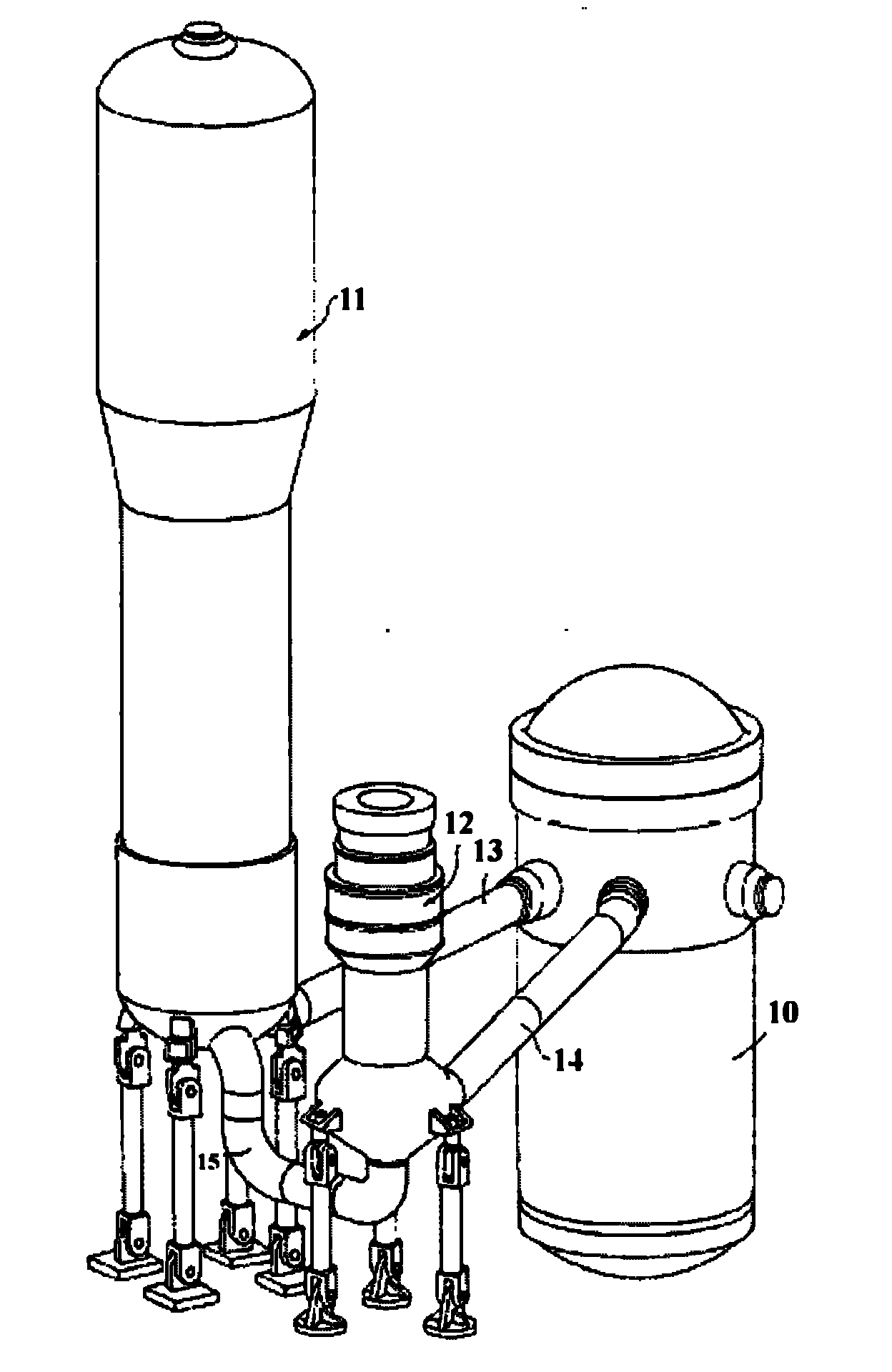
[0038] Such as Figure 5 As shown, the steam generator 11 of the reactor coolant system of the pressurized water reactor nuclear power plant shipped out of the factory has the main pipe hot section elbow 16 and the main pipe transition section elbow 17 respectively welded at the primary circuit nozzle of the lower head.

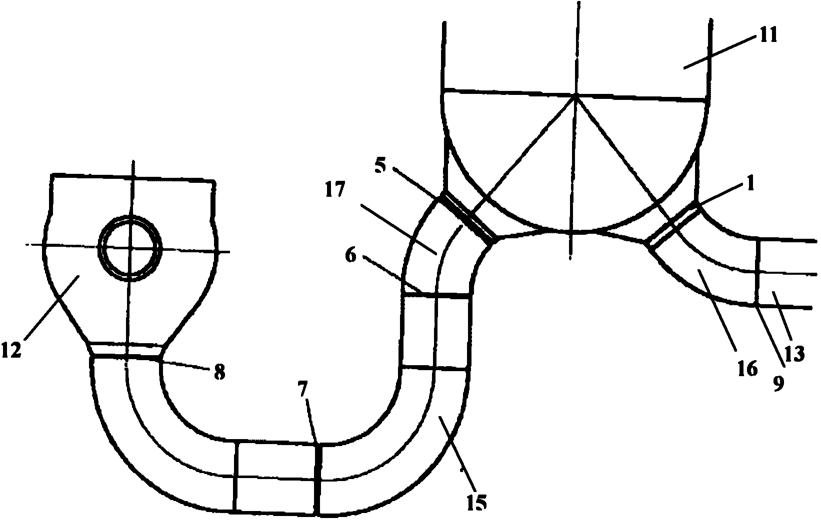
[0039] Such as Figure 8 As shown, the hot section 13 of the main pipeline of the reactor coolant system of the pressurized water reactor nuclear power plant is a straight pipe, excluding the elbow 16 of the original hot section of the main pipeline. Such as Figure 9 As shown, the main pipeline transition section 15 of the reactor coolant system of the PWR nuclear power plant is composed of two sections of pipelines, excluding the original main pipeline transition section elbow 16 .

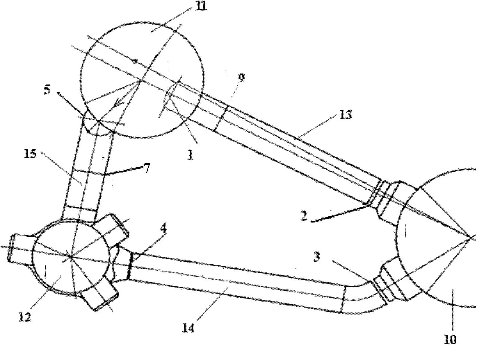
[0040] Such as figure 1 , figure 2 , image 3 As shown, use Figure ...


PUM


Abstract

The invention discloses a method for mounting a main return loop of a nuclear power station pressurized water reactor coolant system, which is characterized in that: a main pipeline heat section bend (16) and a main pipeline transition section bend (17) are welded at a loop nozzle of a lower seal end of the used steam generator (1); during mounting, a welding line (9) between a main pipeline heat section (13) and the main pipeline heat section bend (16) on the lower part of the steam generator (11) and a welding line (2) between the main pipeline heat section (13) and a reactor pressure container (10) can be assembled and welded simultaneously. In addition, the working amount for a welding line (5) is reduced during mounting. The mounting method can better control and guarantee the assembling and welding quality, improve the working efficiency, reduce the mounting time, and shorten the construction period.

Description

technical field [0001] The invention belongs to the field of equipment-pipelines, and in particular relates to a method for a main pipeline and a main circuit of a reactor coolant system of a pressurized water reactor nuclear power plant. Background technique [0002] The main circuit of the reactor coolant system is the core key equipment of the pressurized water reactor nuclear power plant. A loop of the main circuit of the reactor coolant system of a pressurized water reactor nuclear power plant is usually composed of reactor pressure vessel, steam generator, main pump, hot section of main pipeline, cold section of main pipeline, transition section of main pipeline and other connections. The installation of the reactor coolant system loop occupies a critical path in the construction of a pressurized water reactor nuclear power plant, which has an important impact on the completion of the nuclear power plant construction on schedule. During on-site installation, the one-l...

Claims


Application Information

Patent Timeline
Patent Type & Authority Applications(China)
IPC IPC(8): F22B1/02G21C13/02
CPCY02E30/40Y02E30/30
Inventor 于坚王恒石立波董安郭利峰
Owner CHINA NUCLEAR POWER ENG CO LTD
Why Eureka
Try Eureka