High-brightness controllable pseudo-thermal light source based on liquid crystal light valve modulation

A technology of liquid crystal light valve and pseudothermal light source, which is applied in the field of high-brightness controllable pseudothermal light source, can solve the problems of poor repeatability, difficult precise calibration, large mechanical changes of ground glass sheets, etc., and achieve the effect of small energy loss

Active Publication Date: 2010-09-22
SHANGHAI INST OF TECHNICAL PHYSICS - CHINESE ACAD OF SCI
View PDF3 Cites 5 Cited by
  • Summary
  • Abstract
  • Description
  • Claims
  • Application Information

AI Technical Summary

Problems solved by technology

In 2006, in order to overcome the problem that the continuous pseudothermal light source does not meet the cross-spectrum purity conditions of the real thermal optical field, Han Shensheng and others from the Shanghai Institute of Optics and Fine Mechanics of the Chinese Academy of Sciences invented a high-brightness pulsed pseudothermal light source [see Liu Honglin , Zhang Minghui, Wei Qing. Abstracts of the Twelfth National Conference on Quantum Optics. 2006.]
[0004] 1. There is a large mechanical change in the rotating frosted glass sheet, which causes inconvenience to the actual engineering application
[0005] 2. The repeatability of the experiment is poor, and it is difficult to accurately calibrate

Method used


Image

  • High-brightness controllable pseudo-thermal light source based on liquid crystal light valve modulation
  • High-brightness controllable pseudo-thermal light source based on liquid crystal light valve modulation
  • High-brightness controllable pseudo-thermal light source based on liquid crystal light valve modulation

Examples


Embodiment Construction

[0024] The present invention will be further described below in conjunction with the embodiments and accompanying drawings, but the protection scope of the present invention should not be limited thereby.

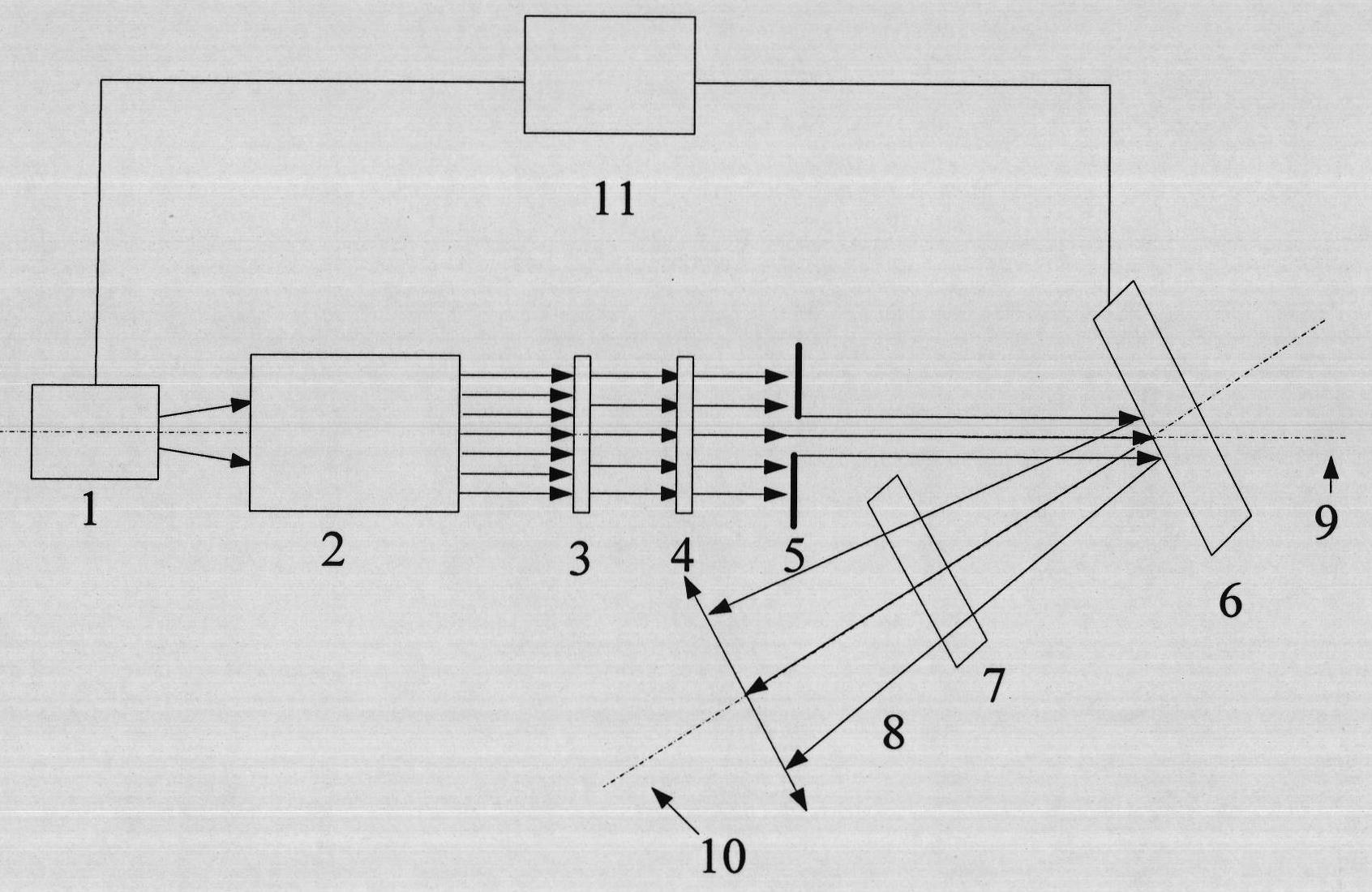
[0025] see figure 1 , figure 1 It is a structural block diagram of the high-brightness controllable pseudothermal light source device based on the liquid crystal light valve modulation method of the present invention, which is also an embodiment of the present invention. It can be seen from the figure that the high-brightness controllable pseudothermal light source based on the liquid crystal light valve modulation of the present invention consists of Including pulsed laser 1, adjustable beam expander collimation system 2, polarizer 3, first analyzer 4, adjustable aperture stop 5, liquid crystal light valve 6, second analyzer 7 and liquid crystal light valve control System 11, the pulsed laser 1, the adjustable beam expander collimation system 2, the polarizer 3, the first...


PUM


Abstract

The invention discloses a high-brightness controllable pseudo-thermal light source based on liquid crystal light valve modulation, which comprises a pulsed laser, an adjustable beam expanding and collimating system, a polarizer, a first analyzer, an adjustable aperture diaphragm, a liquid crystal light valve, a second analyzer and a liquid crystal light valve control system. The pulsed laser, the adjustable beam expanding and collimating system, the polarizer, the first analyzer and the adjustable aperture diaphragm are arranged on the same optical axis. The optical axis is arranged on the incident light optical axis of the liquid crystal light valve. The second analyzer is arranged on the reflected light optical axis of the liquid crystal light valve corresponding to the incident light optical axis. Laser light output by the laser finally irradiates the liquid crystal light valve controlled by a liquid crystal light valve control system. Through controlling the liquid crystal light valve, a dynamic speckle field, i.e. a pseudo-thermal light field is obtained. The thermal fluctuation of the high-brightness controllable pseudo-thermal light source produced by the invention can be truly recorded by the photoelectric detection system of a limited transmission band, the cross spectrum purity conditions satisfying a true-thermal light field can be obtained through controlling RGB images loaded on the liquid crystal light valve and the pseudo-thermal light field produced at any time is controllable.

Description

technical field [0001] The invention relates to an optical component and an optical system, in particular to a high-brightness controllable pseudothermal light source based on liquid crystal light valve modulation. Background technique [0002] In view of the two basic difficulties in the experimental measurement of thermo-optic fluctuations: first, the coherence time of thermo-optic light is very short, even for the quasi-monochromatic light emitted by the best line spectrum light source, the coherence time can only reach 10 -11 -10 -10 second; secondly, the response time of existing photodetectors reaches 10 seconds at the fastest -9 Second. Therefore, the existing photodetectors cannot measure the instantaneous intensity of thermal optical field fluctuations [see Qi Kangnan, Qin Kecheng, Cheng Lu. Introduction to Statistical Optics, P410]. [0003] In order to overcome these two difficulties, Martienssen and Spiller invented a continuous pseudothermal light source in 1...

Claims


Application Information

Patent Timeline
Patent Type & Authority Applications(China)
IPC IPC(8): G01J1/08G02F1/13
Inventor 秦洁心刘世超舒嵘黄庚华韩申生陈弈沈夏
Owner SHANGHAI INST OF TECHNICAL PHYSICS - CHINESE ACAD OF SCI
Why Eureka
Try Eureka