
Method for preparing double-sided PN junction solar battery

A technology of solar cells and PN junctions, which is applied in the manufacture of circuits, electrical components, and final products. It can solve the problems of limited space for solar cell efficiency, low conversion efficiency, and increased conversion efficiency. It is easy to mass produce, The effect of process compatibility and high-efficiency conversion

Active Publication Date: 2010-09-22
锐立平芯微电子(广州)有限责任公司
View PDF0 Cites 17 Cited by
  • Summary
  • Abstract
  • Description
  • Claims
  • Application Information

AI Technical Summary

Problems solved by technology

[0003] At present, the conversion efficiency of crystalline silicon cells is not very high (mass production can reach 17%), and the price is expensive. However, crystalline silicon cells currently account for more than 90% of the market share in various solar cells. It will take time to exit the market, so improving conversion efficiency is an effective means to reduce costs
[0004] Conventional means to improve the efficiency of crystalline silicon solar cells are varied, such as the use of selective emitter structures, back surface electric fields, and surface passivation technologies. great difficulty

Method used


Image

  • Method for preparing double-sided PN junction solar battery
  • Method for preparing double-sided PN junction solar battery
  • Method for preparing double-sided PN junction solar battery

Examples


Embodiment Construction

[0035] In order to make the object, technical solution and advantages of the present invention clearer, the present invention will be described in further detail below in conjunction with specific embodiments and with reference to the accompanying drawings.

[0036] In order to further set forth the technical means and effects that the present invention takes for reaching the intended purpose of the invention, the specific implementation is described, and the detailed description is as follows:

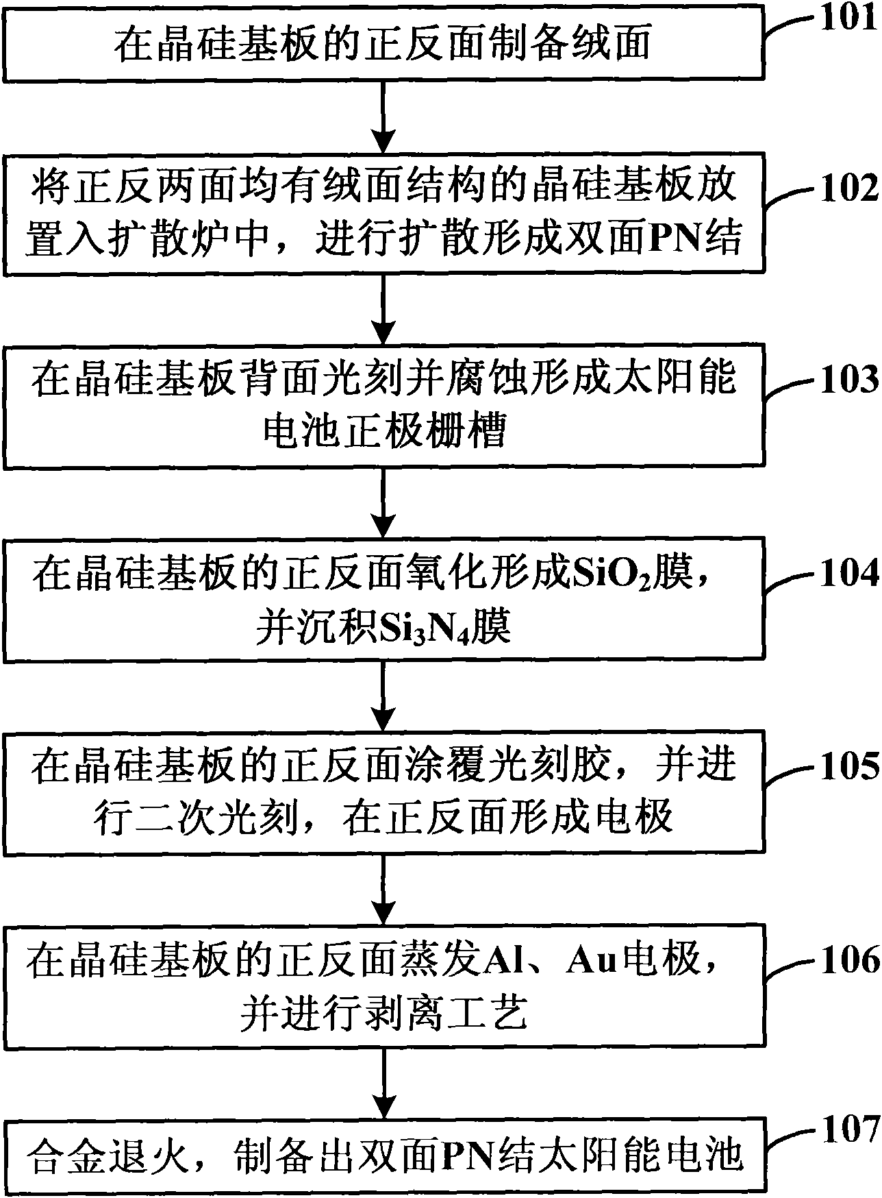
[0037] Such as figure 1 as shown, figure 1 A flow chart of a method for preparing a high-efficiency double PN crystalline silicon battery provided by the present invention, the method includes the following steps:

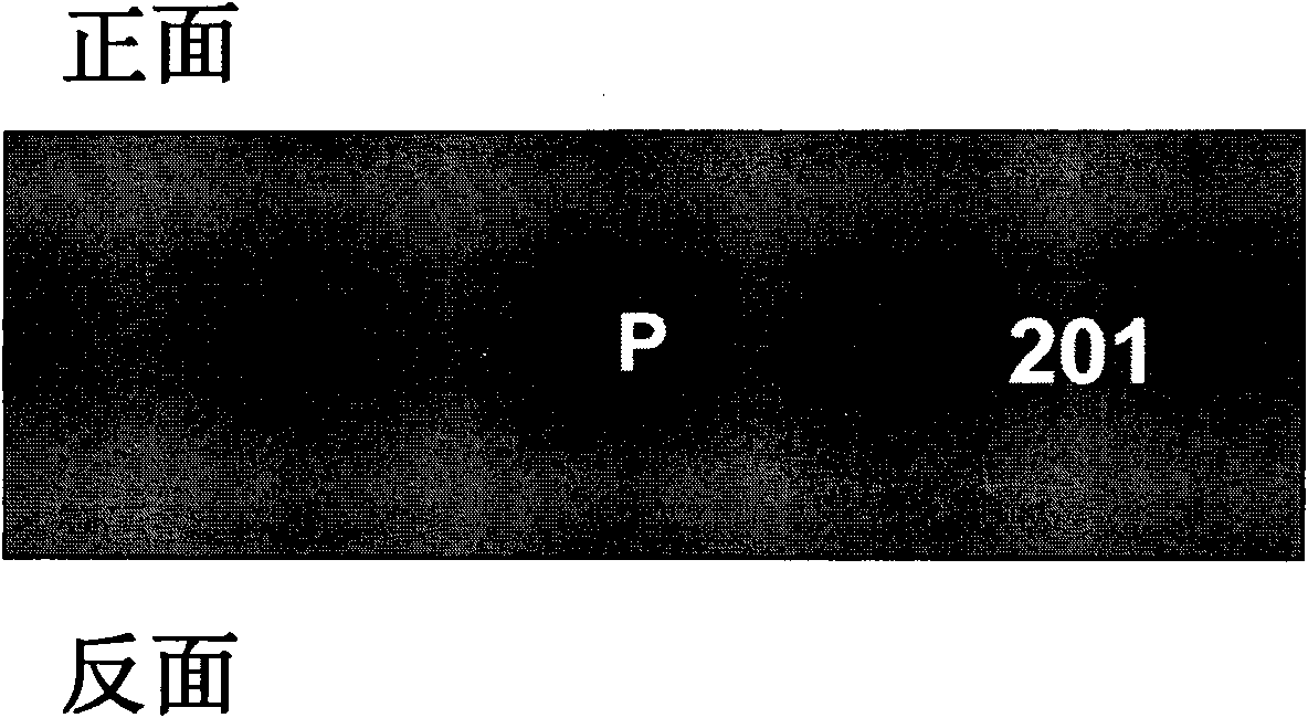
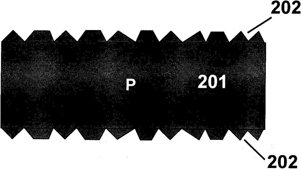
[0038] Step 101: preparing suede on the front and back of the crystalline silicon substrate;

[0039] Step 102: placing the crystalline silicon substrate with the suede structure on the front and back sides in a diffusion furnace, and performing diffusion to form a doubl...


PUM

PropertyMeasurementUnit
Thicknessaaaaaaaaaa
Thicknessaaaaaaaaaa
Thicknessaaaaaaaaaa

Abstract

The invention discloses a method for preparing a double-sided PN junction solar battery, which comprises the following steps of: preparing matte structures on the front side and the back side of a crystal silicon substrate; placing the crystal silicon substrate of which the front side and the back side are provided with the matte structures in a diffusion furnace to perform diffusion so as to form a double-sided PN junction structure; photoetching and corroding the back side of the crystal silicon substrate to form a positive electrode gate groove of the solar battery; oxidizing the front side and the back side of the crystal silicon substrate to form SiO2 films, and depositing Si3N4 films; coating a photoresist on the front side and the back side of the crystal silicon substrate, and performing photoetching exposure and development to form positive and negative patterns on the back side of the battery and negative electrode patterns on the front side of the battery; evaporating metal electrodes on the front side and the back side of the crystal silicon substrate, and performing a stripping process; and performing alloy annealing to prepare the double-sided PN junction solar battery. The method uses two PN junctions of a crystal silicon battery for work to finally fulfill the aim of efficient conversion, has fewer process steps, is simple, can be compatible with a process on a large-scale production line, and can realize large-scale production easily.

Description

technical field [0001] The invention relates to the technical field of crystalline silicon (polycrystalline silicon and single crystal silicon, collectively referred to as crystalline silicon) solar cells, in particular to a method for preparing double-sided PN junction solar cells. Background technique [0002] With the rapid increase of the world's population and the rapid development of the economies of various countries, the demand for energy is increasing; due to the limited reserves of fossil energy represented by oil and coal, according to the current consumption, it will be exhausted in a few decades. At the same time, the current frequent use of fossil energy has caused serious air pollution and the greenhouse effect, so the demand for clean and renewable energy is becoming more and more urgent. As a kind of clean energy, solar cells have been developed rapidly. Since Bell Laboratories reported the first commercialized Si solar cell in 1954, various solar cells hav...

Claims


Application Information

Patent Timeline
IPC IPC(8): H01L31/18
CPCY02P70/50
Inventor 贾锐朱晨昕陈晨李维龙张培文李昊峰赵盛杰刘明
Owner 锐立平芯微电子(广州)有限责任公司
Learn More