Motor assembly as well as positioning installation method thereof

A motor and assembly technology, applied in the field of motor assembly and its positioning and installation, can solve the problems of increased cost, high requirements on gasket materials, and large motor string movement, etc., to reduce friction and motor string movement, reduce material and Processing cost, effect of reducing skew and vibration

Inactive Publication Date: 2010-09-22
SHENZHEN CREATIVE & BRIGHT PRECISION PLASTIC MOLD
View PDF4 Cites 7 Cited by
  • Summary
  • Abstract
  • Description
  • Claims
  • Application Information

AI Technical Summary

Problems solved by technology

[0003] The disadvantage of this existing design is that when the armature shaft drives the gear of the gearbox through the worm, it will be subjected to the reaction force of the gear
The disadvantage of this solution is that the accuracy level of parts such as the iron shell and the armature shaft is high, and the material requirements of the gasket are also high, resulting in higher material and processing costs for the motor.
[0005] Another solution to the above problem is to use a steel ball at the bottom of the gearbox and the bottom of the iron case. The steel ball can reduce friction, but the dimensional accuracy of the entire assembly chain is very high. In order to match the iron case and the gearbox, Usually, the second processing of the armature shaft is required, resulting in an increase in cost; at the same time, since the contact between the armature shaft and the steel ball is metal-to-metal contact, after a period of wear and tear, the noise is relatively large, and the serial motion of the motor is also large

Method used


Image

  • Motor assembly as well as positioning installation method thereof
  • Motor assembly as well as positioning installation method thereof
  • Motor assembly as well as positioning installation method thereof

Examples


Embodiment Construction

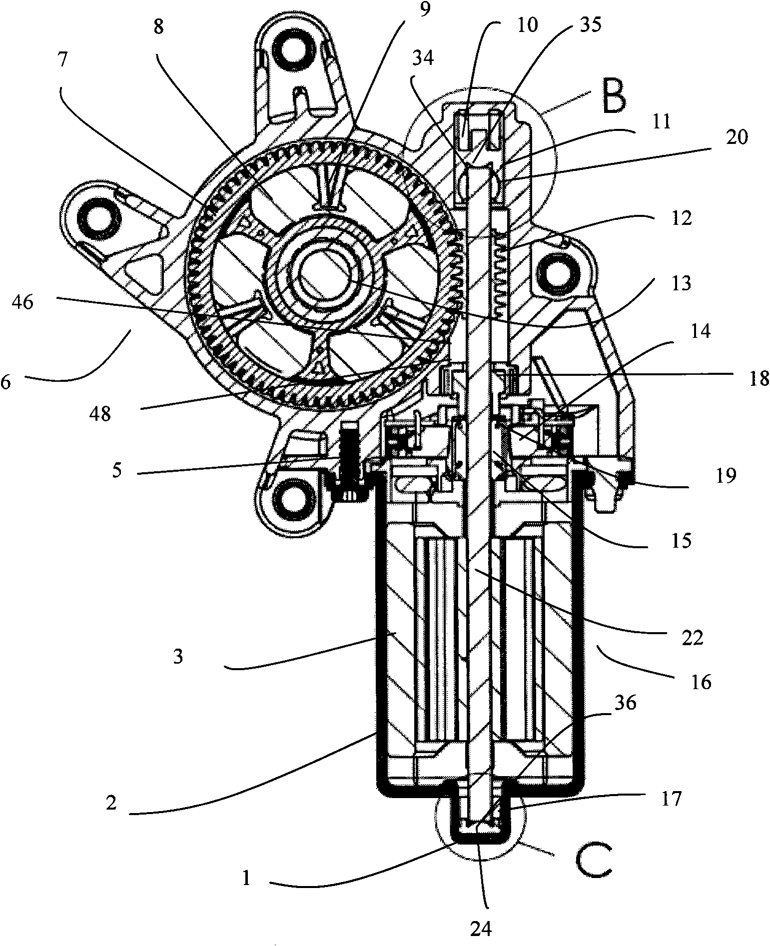
[0044] In order to further elaborate the technical means and effects adopted by the present invention to achieve the predetermined purpose, please refer to the following detailed description and accompanying drawings of the present invention. It is believed that the purpose, characteristics and characteristics of the present invention should be able to gain a deep and specific understanding from this , however, the accompanying drawings are provided for reference and illustration only, and are not intended to limit the present invention.

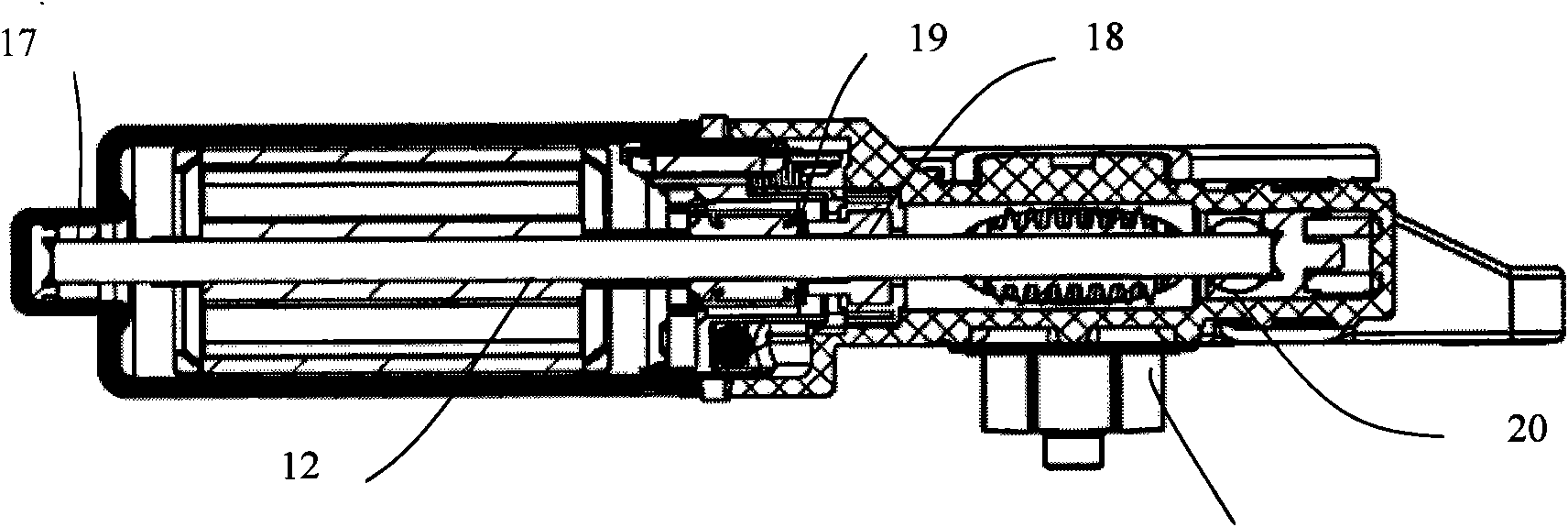
[0045] Such as Figure 1-4As shown, the present invention provides a motor assembly, which includes: a motor 16, and a gearbox 6 connected to the motor 16, the motor 16 includes a motor housing 2, an armature shaft 22 installed in the motor housing 2, The thrust plate 1 installed on the bottom of the motor housing 2, and the straight bearing 17 press-fitted on the thrust plate 1; the gear box 6 includes an output gear shaft 21, and a drive p...


PUM


Abstract

The invention relates to a motor assembly and a location and installation method thereof. The motor assembly comprises a motor and a gear box connected with the motor, wherein, the motor comprises a motor shell, an armature shaft arranged in the motor shell, a push stopping plate arranged at the bottom of the motor shell and a straight bearing arranged on the push stopping plate; the gear box comprises an output gear shaft, a drive disk which drives the output gear shaft to rotate, a gear, a butter cushion arranged in the inner cavity of the gear, a straight bearing assembly and a supporting seat provided with a bearing; the push stopping plate and the supporting seat are respectively provided with a spherical surface; the armature shaft passes through the straight bearing, the straight bearing assembly and the inner hole of the bearing in the supporting seat in sequence, and the two end surfaces of the push stopping plate are respectively contacted with the spherical surfaces of the push stopping plate and the supporting seat; the armature shaft is provided with a worm and is provided with a commutator; the worm is positioned between the straight bearing assembly and the supporting seat; the worm drives the gear in the gear box to rotate along the rotation of the armature shaft. The invention can reduce string vibration of motor output shaft at rating load, lower the noise of the motor, and improve output efficiency of the motor.

Description

technical field [0001] The invention relates to a motor assembly, in particular to a motor assembly capable of improving the output efficiency of the motor and a positioning and installation method thereof. Background technique [0002] Existing motor assemblies generally include a motor and a gearbox connected together, wherein the armature shaft of the motor protrudes from a bearing on the motor end cover and reaches a bearing located in a bore of the gearbox. The armature shaft between the bearings on the end cap and the bearings in the gearbox bore drives the gears of the gearbox through a worm mounted on the armature shaft to rotate with the armature shaft. [0003] The defect of this existing design is that: when the armature shaft drives the gear of the gearbox through the worm, it will be subjected to the reaction force of the gear. This reaction force is decomposed into axial and radial parts through the worm, and the axial force will be transmitted to the bottom o...

Claims


Application Information

Patent Timeline
Patent Type & Authority Applications(China)
IPC IPC(8): H02K7/116H02K5/16H02K5/24H02K15/00
Inventor 唐宪
Owner SHENZHEN CREATIVE & BRIGHT PRECISION PLASTIC MOLD
Why Eureka
Try Eureka