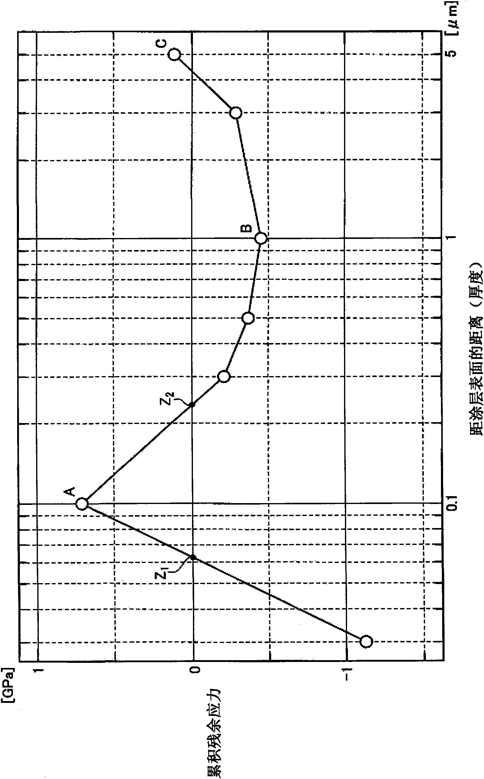
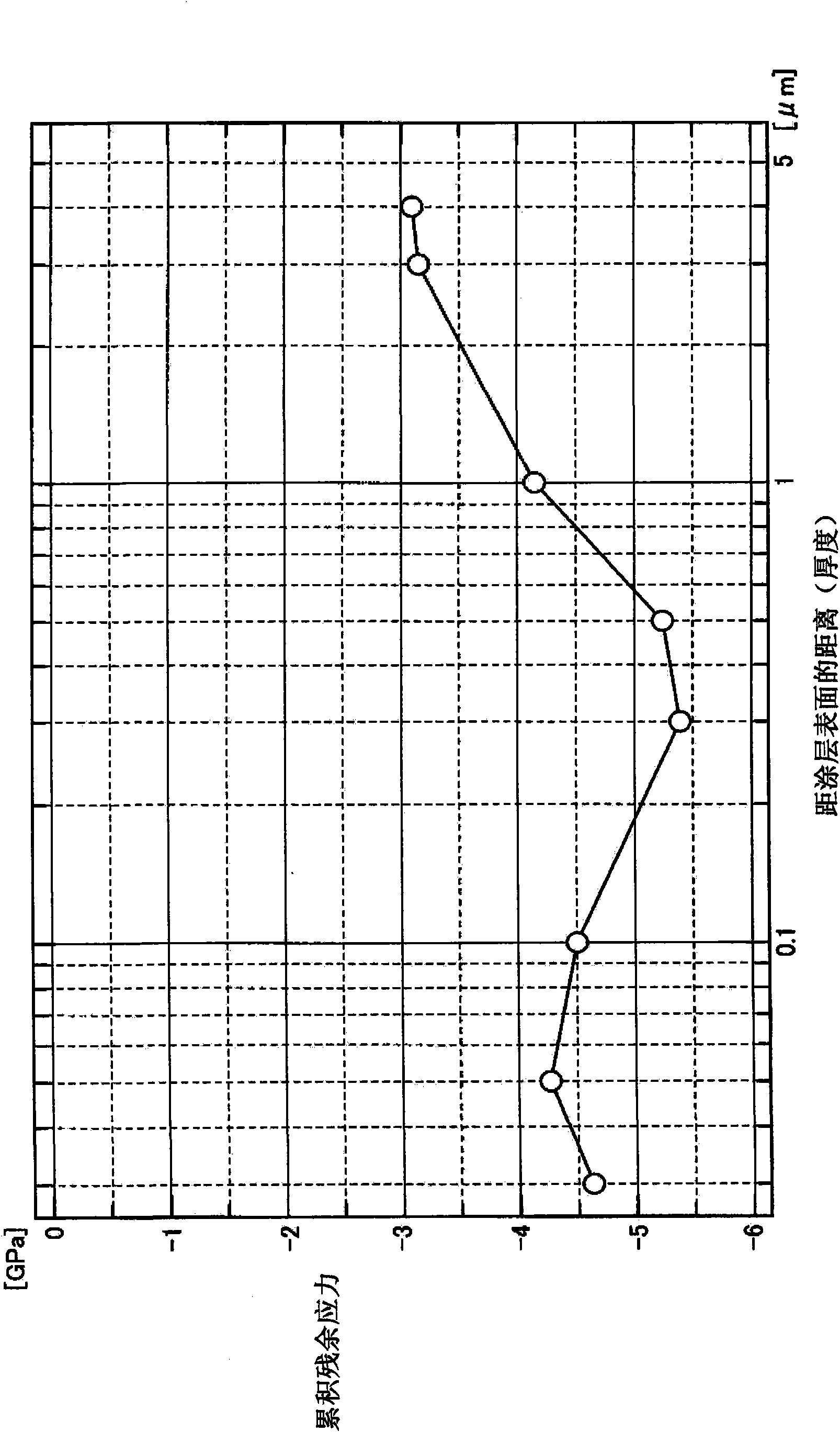
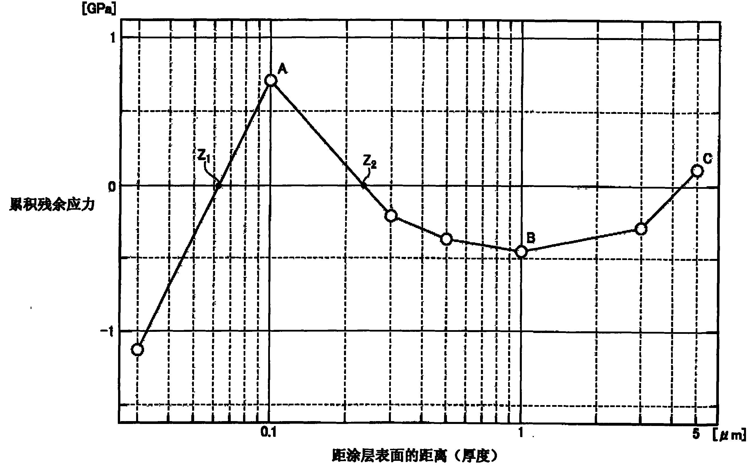
Surface coated cutting tool
A cutting tool, surface area technology, applied in manufacturing tools, tools for lathes, metal material coating processes, etc., can solve the problems of reduced film strength, increased surface roughness, and reduced peel resistance, achieving excellent Abrasion resistance, the effect of reducing the possibility
- Summary
- Abstract
- Description
- Claims
- Application Information
AI Technical Summary
Problems solved by technology
Method used
Image
Examples
Embodiment 1 to 6 and comparative example 1 to 4
[0081] In the following Examples 1-6, the formed coatings were all layers having a single composition, but a coating whose composition was different from those in these Examples was used, or two or more coatings having different compositions were used. Coatings formed from layers, or using at least a portion of a coating having a super multilayer structure, may also provide similar benefits.
[0082] Production of surface-coated cutting tools
[0083] First, indexable inserts for cutting (base material No. 1 and base material No. 2) formed of materials shown in Table I below and having a tool shape shown in Table I below were prepared as the surface-coated inserts. The substrates of the cutting tools (in preparation for the various characterization methods described below) were then mounted on cathodic arc ion plating equipment. The substrates were formed of cemented carbide and contained WC grains with an average grain size (those grains on the surface of the substrate (at t...
Embodiment 7 to 12 and comparative example 5 to 10
[0113] Two kinds of cemented carbide substrates were prepared as the substrates of the coated cutting tools (one for each property evaluation method described later), and the compositions of the cemented carbide substrates were both WC-2TaC-0.7Cr 3 C 2 -7Co (wherein the numerical value represents the weight percentage, and the remainder is WC), but contains WC grains of different grain sizes (the average grain size of the WC grains in Examples 7, 9 and 11 is 1.2 μm, and in Examples 8 and 10 and 12, the average grain size of the WC grains is 3.5 μm). The substrate was fabricated into indexable cutting inserts having the tool shapes shown in Table I. These substrates were mounted on cathodic arc ion plating equipment.
[0114] Subsequently, the internal pressure of the chamber of the apparatus was lowered using a vacuum pump, and at the same time, the temperature of the substrate was raised to 450° C. using a heater installed in the apparatus. The chamber was evacuated until ...
Embodiment 13 to 15 and comparative example 11
[0129] Preparation of surface-coated cutting tools
[0130] First, indexable inserts for cutting (base material No. 1 and base material No. 2) formed of the materials shown in the above Table I and having the shape of the tool shown in the above Table I were prepared as the surface-coated inserts. The substrates of the cutting tools (in preparation for the various characterization methods described below) were then mounted on cathodic arc ion plating equipment. The substrates were formed of cemented carbide and contained WC grains with an average grain size (those grains on the surface of the substrate (at the interface with the coating)) as shown in Table I.
[0131] Subsequently, the internal pressure of the chamber of the apparatus was lowered using a vacuum pump, and the temperature of the substrate was raised to 450° C. using a heater installed in the apparatus. The chamber was evacuated until its internal pressure reached 1.0 x 10 -4 Pa.
[0132] Next, argon gas was i...
PUM
| Property | Measurement | Unit |
|---|---|---|
| thickness | aaaaa | aaaaa |
| thickness | aaaaa | aaaaa |
| thickness | aaaaa | aaaaa |
Abstract
Description
Claims
Application Information
 - R&D
- Intellectual Property
- Life Sciences
- Materials
- Tech Scout
- Unparalleled Data Quality
- Higher Quality Content
- 60% Fewer Hallucinations
Browse by: Latest US Patents, China's latest patents, Technical Efficacy Thesaurus, Application Domain, Technology Topic, Popular Technical Reports.
© 2025 PatSnap. All rights reserved.Legal|Privacy policy|Modern Slavery Act Transparency Statement|Sitemap|About US| Contact US: help@patsnap.com


