
System level testing for substation automation systems

A technology for substations and power systems, applied in the field of realization and testing of interlocking functionality, capable of solving problems such as cost, space, and limitations of complex testing equipment

Active Publication Date: 2010-09-22
HITACHI ENERGY LTD
View PDF1 Cites 10 Cited by
  • Summary
  • Abstract
  • Description
  • Claims
  • Application Information

AI Technical Summary

Problems solved by technology

However, since a full number of IEDs requires increasingly complex test equipment and due to cost and space constraints, not all IEDs of a particular substation are installed for FAT

Method used


Image

  • System level testing for substation automation systems
  • System level testing for substation automation systems
  • System level testing for substation automation systems

Examples


Embodiment Construction

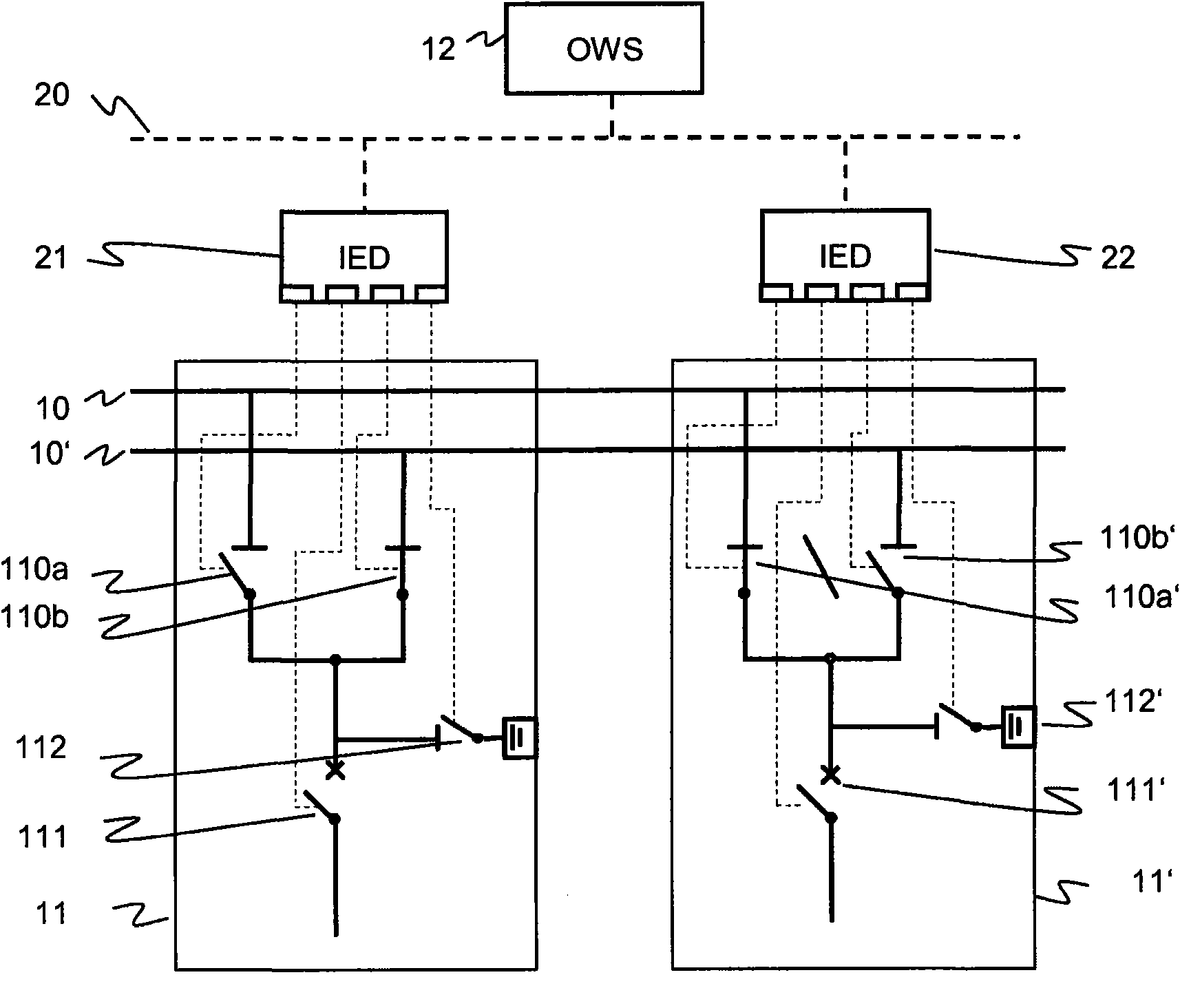
[0028] figure 1 A single circuit diagram showing a portion or section of an exemplary substation at a hypothetical voltage level of eg 110 kV and exemplary substation automation (SA) and / or secondary equipment. The model of the switch yard at single line level contains the respective topological electrical connections between the primary devices. The substation comprises a double busbar configuration in which two busbars 10, 10' feed two bays 11, 11' through disconnectors 110a to 110'b. Each bay includes a circuit breaker 111, 111' and an earthing switch 112, 112'. The corresponding excerpt of the substation automation system depicts with dotted lines the communication network 20 and the two IEDs 21, 22, both of which accommodate CSWI level (switch control) logical nodes. Each logical node is assigned to the figure 1 One of the aforementioned switching devices 110a to 112' is indicated by the thin dashed line in . An operator workstation 23 is also depicted.

[0029] The ...


PUM


Abstract

The present invention proposes that protection, measurement and control IEDs in a substation compute, according to interlocking rules or physical principles as well as a knowledge of the dynamic topology of the substation, for every switch they control if that switch may be operated safely, in contrast to a conventional and separate programming of the interlocking logic for each IED. To this purpose, the IEDs have access to the substation electrical topology, to the real-time information generated by other IEDs, and to the rules for interlocking. The invention takes advantage of a standardized Substation Configuration Description (SCD) of the substation for which the SA system is intended, as well as of a standardized description of the implemented device functions or capabilities of an individual IED. In particular, the substation topology is available from the substation configuration description (SCD file in IEC 61850 format), the real time information about the position of switches and line voltage / current can be read over the IEC 61850 protocol and the rules are available in script form. This concept applies both to simulated and real devices, and greatly increases system testing possibilities by supporting an efficient configuration of a simulation.

Description

technical field [0001] The invention relates to the field of Substation Automation (SA) systems for substations in high and medium voltage power grids. More specifically, it relates to the implementation and testing of interlocking functionality in Intelligent Electronic Devices (IEDs) of SA systems. Background technique [0002] An electric power system includes an electric power transmission and / or distribution grid interconnecting geographically separated areas, and a plurality of substations at nodes of the power grid. A substation includes equipment for transforming voltage and for switching connections between the various lines of the power grid. Generation and load flow to consumers is managed by a central Energy Management System (EMS) and / or monitored by a Supervisory Control and Data Acquisition (SCADA) system located in a Network Control Center (NCC). [0003] Substations in high and medium voltage power networks comprise for example cables, lines, busbars, powe...

Claims


Application Information

Patent Timeline
Patent Type & Authority Applications(China)
IPC IPC(8): G01R31/327H02H11/00
CPCH02J13/0062G01R31/3272Y02E60/723Y04S40/124Y04S10/18H02H11/008Y02E60/7838Y02E60/724Y04S10/16H02J13/00016H02J13/00034H02J13/0004Y02E60/00
Inventor H·基尔曼M·奥布里斯特W·威默
Owner HITACHI ENERGY LTD
Learn More