Bucket rod slot plate forming method of 6-ton digging machine

A forming method and excavator technology, which is applied in the field of processing bending parts of construction machinery, can solve problems such as dimensional errors, inability to guarantee weld quality requirements, and affect the quality of sticks, and achieve the effect of accurate dimensions and meeting welding quality requirements

Inactive Publication Date: 2010-09-29
龙工(上海)机械制造有限公司 +2
View PDF0 Cites 7 Cited by
  • Summary
  • Abstract
  • Description
  • Claims
  • Application Information

AI Technical Summary

Problems solved by technology

Because the previous process of the arm channel plate was not fine enough, there are many problems after bending and forming: first, the position and size error of the three shaft holes on the arm channel plate is relatively large
The void formed by the circular crack relief hole 2-3 needs repair welding, which cannot guarantee the quality requirements of full penetration of the weld seam
At the same time, the effect of crack arrest is not ideal and there are still cracks. The existence of these problems directly affects the quality of the stick

Method used


Image

  • Bucket rod slot plate forming method of 6-ton digging machine
  • Bucket rod slot plate forming method of 6-ton digging machine
  • Bucket rod slot plate forming method of 6-ton digging machine

Examples


Embodiment 1

[0025] A method for forming a 6-ton excavator arm groove plate provided by the invention, the steps are:

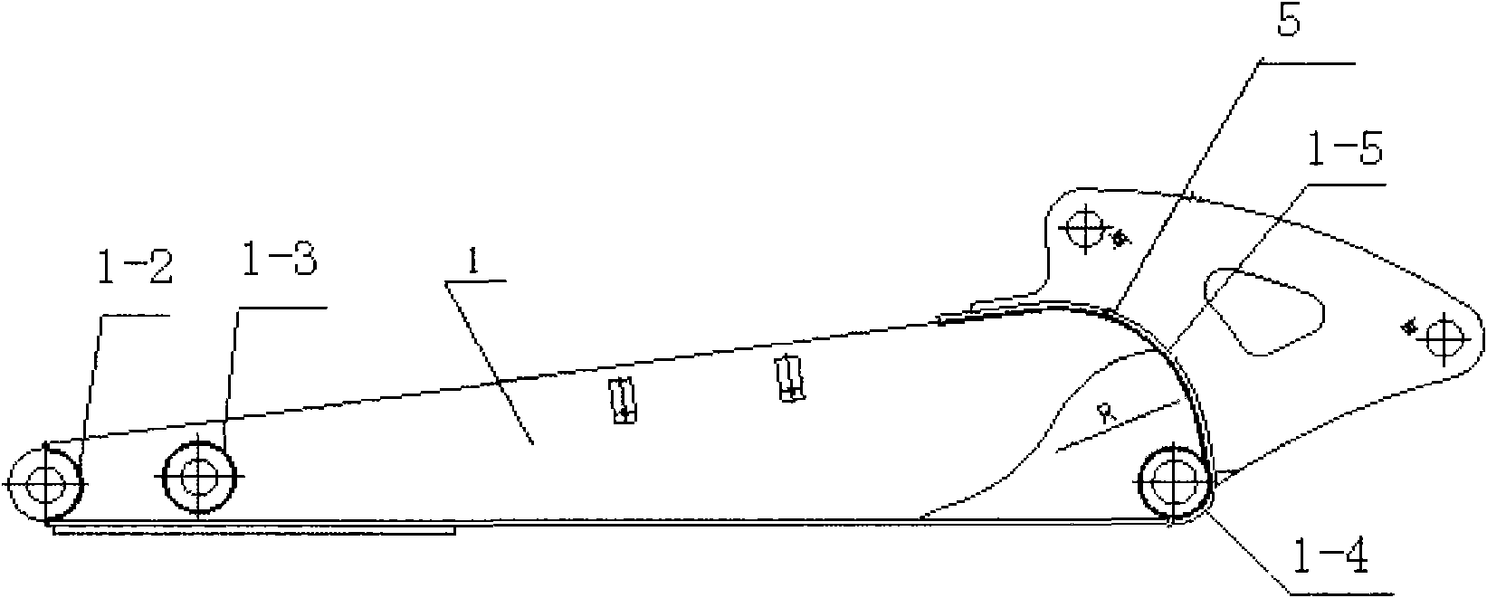
[0026] Step 1. The bending part is extended due to the compression of the plate during the pressing process. The extension length is affected by the different materials, the size of the R angle of the pressing and the thickness of the plate. The unfolded length of the bending part must be determined according to the actual situation. According to item 6 of JB / T5109-2001 sheet metal bending process design specification standard document, the present invention calculates the bending expansion length l of the arm groove plate 1, and the steps are roughly as follows:

[0027] Step 1.1. Take the value of the displacement coefficient x of the neutral layer. In this embodiment, according to r / t=1.33, take bending radius r=8mm, plate thickness t=6mm, neutral layer displacement coefficient x=0.34;

[0028] Step 1.2, according to the above value, determine the neutral layer radius...

Embodiment 2

[0037] The difference between this embodiment and Embodiment 1 is that in Step 4, the center position of the arc R of the arm groove plate 1 needs to be moved downward by an amount K=1.5 mm. In step 5, the width b of the transverse relief groove is 4 mm, and the length c is 4 mm. Other steps are identical with embodiment 1.

Embodiment 3

[0039] The difference between this embodiment and embodiment 1 is that in step 4, the center position of the arc R of the arm groove plate 1 needs to be moved down by K=2mm. In step 5, the width b of the transverse relief groove is 7 mm, and the length c is 7 mm. Other steps are identical with embodiment 1.


PUM


Abstract

The invention relates to a bucket rod slot plate forming method of a 6-ton digging machine. The method comprises the following steps: calculating the press bending unfolding length l of a bucket rod slot plate according to a metal plate material press bending process design specification standard; and determining the positions of three shaft holes on the bucket rod slot plate by a geometrograph method through adding the straight line length to the circular arc unfolding length l. The invention is characterized in that the minimum bending edge height h is preserved at the first axial hole; the center position of the circular arc R of the bucket rod slot plate needs to be downwards moved by a distance K between 1.5 and 2 mm; a transverse crack-resistance slot is formed at the end part of the circular arc R of the bucket rod slot plate; a gas flame cutting method, a plasma cutting method, a precision plasma cutting method or a laser cutting method are adopted for baiting; the materials are bended and formed after being cut; and finally, the circular arc at the first axial hole is positioned and cut. The invention has the advantages that the size after the press bending is precise, in addition, no cracking condition occurs, and the welding quality requirement is met. The reasonable cutting methods are reasonably selected according to the requirements, and high quality and high speed of the manufacture of the press bending forming parts can be reached.

Description

technical field [0001] The invention relates to the processing of bending parts of engineering machinery, in particular to a method for forming a 6-ton excavator arm groove plate, which can effectively improve the dimensional accuracy of complex bending parts and maximize the assembly and welding quality of excavator parts The invention belongs to the technical field of processing technology for bucket rod groove plates of 6-ton excavators. Background technique [0002] The 6-ton stick is one of the most important welded structural parts of the excavator, and the main component in the stick is the stick groove plate. Such as Figure 1A and Figure 1B As shown, the bottom of the arm channel plate 1 is sequentially equipped with a first bushing 2, a second bushing 3 and a third bushing 4 from front to back, and a bent plate 5 is installed on the rear end of the arm channel plate 1. Correspondingly, the connecting area 1-2 between the arm channel plate and the first bushing, ...

Claims


Application Information

Patent Timeline
Patent Type & Authority Applications(China)
IPC IPC(8): B23P15/00
Inventor 郑可文陈国良田守训
Owner 龙工(上海)机械制造有限公司
Why Eureka
Try Eureka