Electric air pump

A technology of electric air pumps and pump casings, applied in pumps, piston pumps, pump devices, etc., can solve problems such as low inflation efficiency, damage to driven gears and driving gears, and easy wear of sealing rings, so as to improve inflation efficiency and ensure The effect of air tightness

Active Publication Date: 2010-09-29
NINGBO BRAVO MFG OF INFLATORS & ACCESSORIES
View PDF9 Cites 9 Cited by
  • Summary
  • Abstract
  • Description
  • Claims
  • Application Information

AI Technical Summary

Problems solved by technology

[0006] 1. It detects the pressure in the air pipe in real time through the pressure sensor installed in the air outlet pipe. When the pressure value reaches the preset pressure value transmitted to the single-chip microcomputer control module, it switches the motor to work and realizes the conversion of the inflation mode. Since the electric air pump is generally Using the battery as the working power source, when the power of the battery is insufficient, the centrifugal fan will inflate the inflated equipment, and the pressure of the inflated equipment will not reach the pressure value preset by the pressure sensor, so the electric air pump cannot complete the switching of the inflation mode, that is The centrifugal fan always inflates the inflatable equipment, but the piston inflatable structure does not work, so the electric air pump cannot continue to inflate the inflatable equipment, resulting in the electric air pump not working normally; When the pressure reaches the preset pressure value of the pressure sensor, the centrifugal fan can continue to inflate the inflatable equipment at this time, but because the set pressure value is reached, the inflation method is converted to a piston inflation method, which will affect the inflation efficiency of the entire inflation process
[0007] 2. In addition to the air outlet, an air inlet is provided at the front end of the cylinder liner, and a one-way valve structure that only allows outside air to enter the cylinder liner is installed at the air inlet, so the The space for setting the aforementioned one-way valve structure is reserved, so that when the piston moves forward in the cylinder liner, some gas will exist in the space where the aforementioned one-way valve structure is installed at the air inlet, so that This part of the gas cannot be discharged from the air outlet to inflate the inflatable device, so its inflation efficiency is low
[0008] 3. In addition, the sealing ring used to seal between the piston and the cylinder liner in the existing air pump is easy to be worn, so that air leakage occurs during the inflation process, which further affects the inflation efficiency
[0009] 4. The piston driving structure of the existing electric air pump has the following problems. During the rotation of the driven gear, the position where the driven gear is connected to the piston rod will be affected by the thrust of the piston rod, while other positions of the driven gear will not be responsible. Due to the external thrust, the force on the driven gear is uneven during the rotation process, and the driven gear is prone to vibration during the rotation process, resulting in a large noise during the driving process of the air pump, and the bite of the driving gear and the driven gear will occur. Loose, and damage the driven gear and driving gear, reducing the service life of the electric air pump

Method used


Image

  • Electric air pump
  • Electric air pump
  • Electric air pump

Examples


Embodiment Construction

[0031] The present invention will be further described in detail below in conjunction with the accompanying drawings and embodiments.

[0032] Such as Figure 1-9 Shown is a preferred embodiment of the present invention.

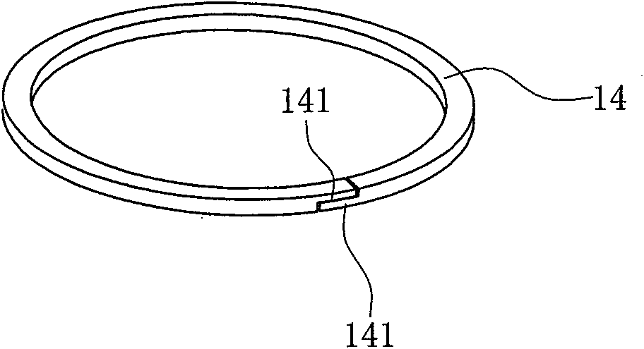
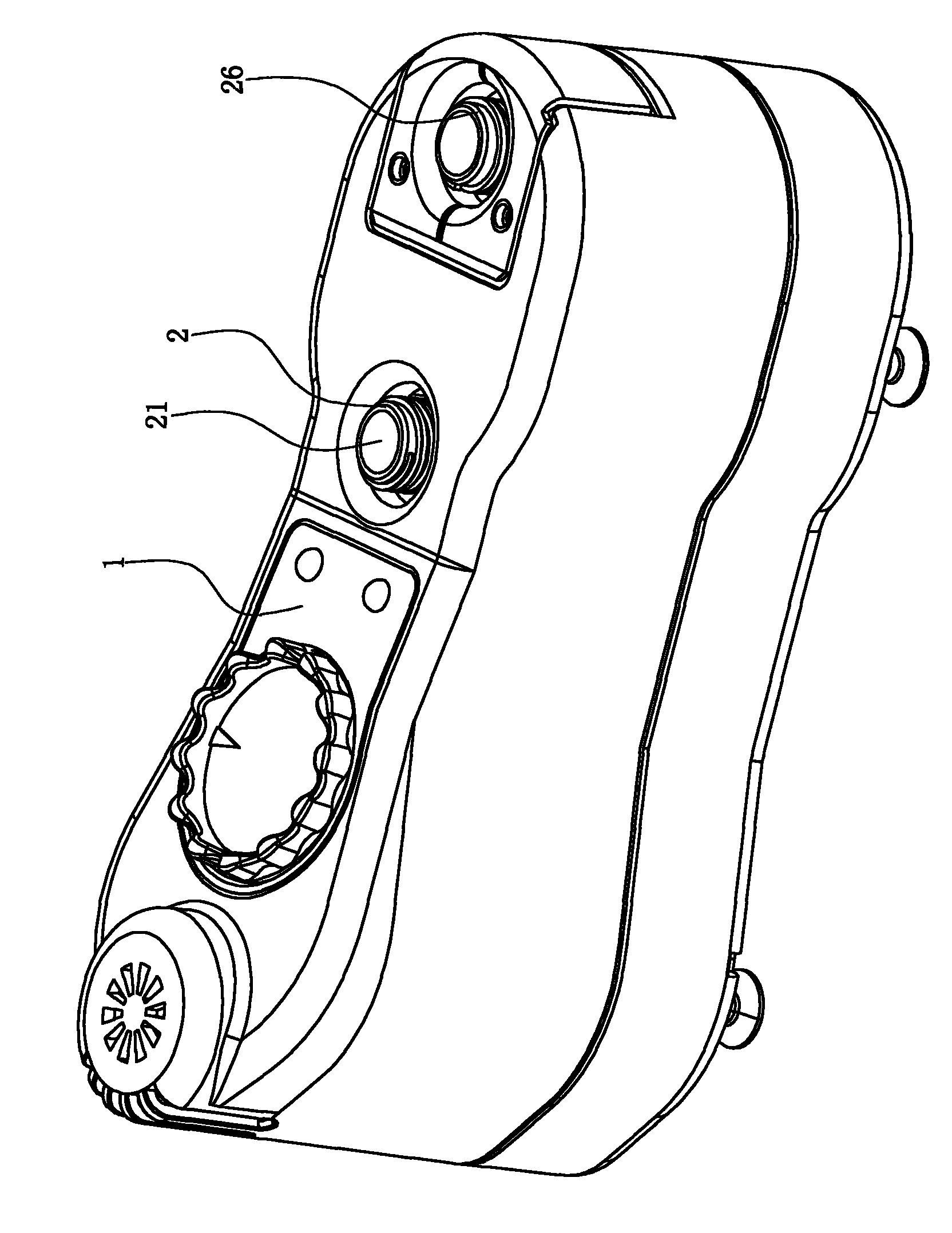
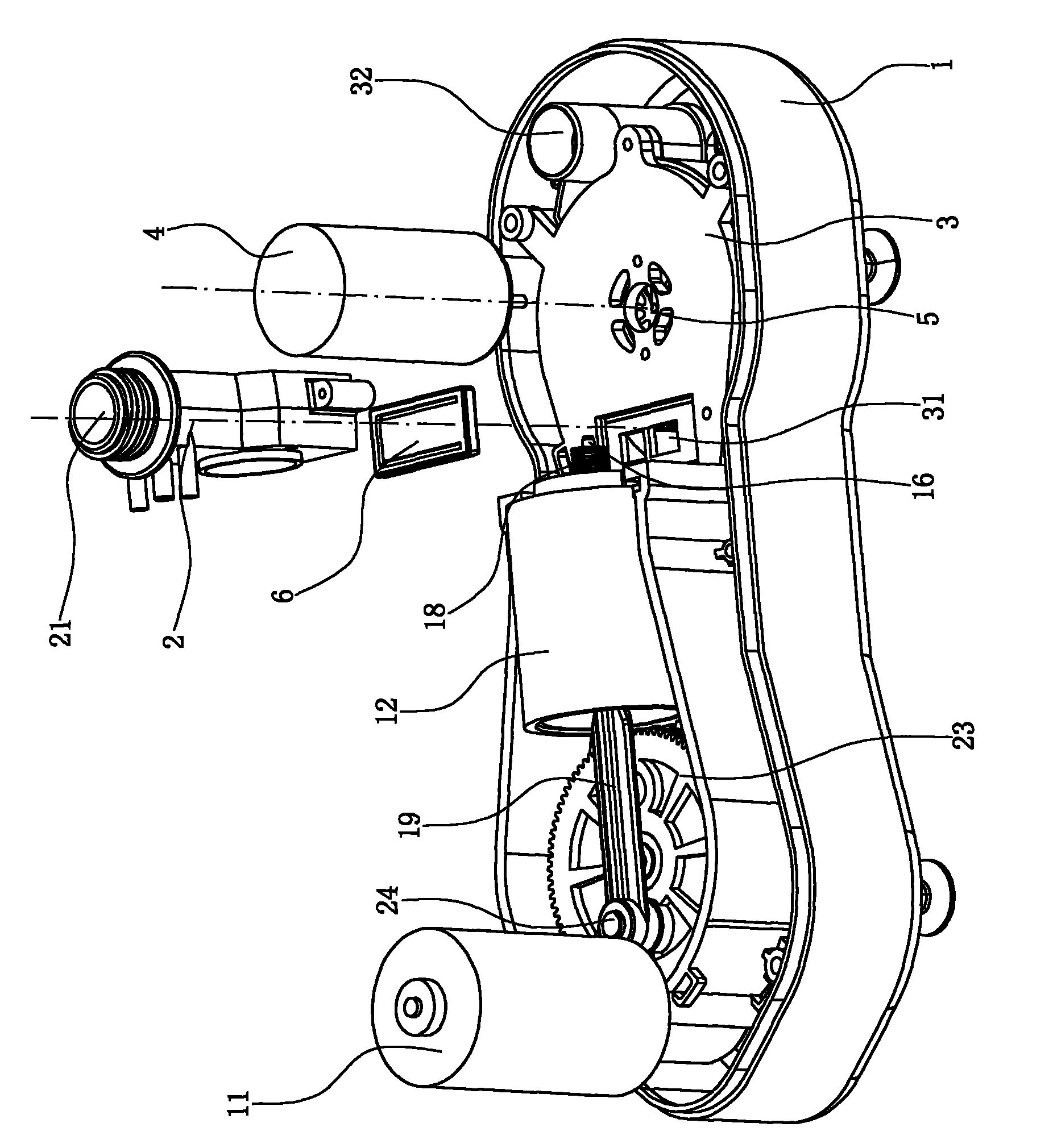
[0033] An electric air pump, including a piston-type inflatable structure set in the casing 1 and driven by the first motor 11, such as Figure 5 , 6 , 8, and 9, the piston-type inflatable structure includes a cylinder liner 12 arranged in the shell 1, the front end of the cylinder liner 12 is provided with an air outlet 121, and the air outlet 121 is provided with a one-way valve that only allows the gas in the cylinder liner 12 to discharge. Valve structure, the front end of the cylinder liner is fixed with a joint 2 by screws, the joint 2 extends out of the shell 1, a sealing ring is provided between the joint 2 and the front end of the cylinder liner 12, and the outer periphery of the joint 2 is provided with a convenient and inflatable device There i...


PUM


Abstract

The invention relates to an electric air pump, which comprises a piston type inflating structure and a centrifugal inflating structure which are arranged in a casing, wherein the centrifugal inflating structure comprises a pump casing with an air outlet and an air inlet; a wind wheel is arranged in the pump casing; an air outlet of the piston type inflating structure and the air outlet of the pump casing are connected with a joint; and the joint is internally provided with an inflating hole communicated with the air outlet of the piston type inflating structure and the air outlet of the pump casing. The electric air pump is characterized in that a first unidirectional valve plate which only allows gas in the pump casing to be exhausted to the inflating hole is arranged at the air outlet of the pump casing; an air inlet channel communicated with the air inlet and the outside is arranged at the bottom of the pump casing; a valve port is arranged in the middle of the air inlet channel; a second unidirectional valve plate is arranged at the valve port and is internally provided with a magnet; and a reed switch capable of inducting the magnet only when the second unidirectional valve plate is positioned in a closed state is fixed outside the pump casing. The invention is the electric pump capable of automatically and stably switching the inflating mode according to the real-time pressure in the inflating equipment.

Description

technical field [0001] The invention relates to an electric air pump. Background technique [0002] The existing electric air pump mainly has two structural modes: one is a piston type electric air pump, which includes a shell with an air charging port, and a cylinder liner is fixed inside the shell, and the front end of the cylinder liner is provided with an air inlet and an air outlet. It communicates with the charging port of the shell. The air inlet is provided with a one-way valve structure that only allows outside air to enter the cylinder liner, and the gas outlet is provided with a one-way valve structure that only allows the gas in the cylinder liner to discharge to the charging port. The cylinder liner A piston is arranged inside, and a sealing ring is arranged between the peripheral side of the piston and the inner wall of the cylinder liner for sealing, and a piston driving structure for driving the piston to reciprocate in the cylinder liner is also arranged in ...

Claims


Application Information

Patent Timeline
Patent Type & Authority Applications(China)
IPC IPC(8): F04B35/04F04B39/12F04B39/10F04B53/14
CPCF04B35/04F04B35/01F04B39/102F04B39/121F04B39/123F04B41/06F04D25/084F04D25/166
Inventor 艾玛诺·维多利奥·梅迪契
Owner NINGBO BRAVO MFG OF INFLATORS & ACCESSORIES
Why Eureka
Try Eureka