

Thin film forming apparatus and forming method for thin film
A technology of thin film and annular belt, which is applied in the direction of vacuum evaporation plating, coating, gaseous chemical plating, etc. It can solve the problems of the reduction of mechanical properties of the substrate, the application of thermal load, the deformation of the substrate, etc., and achieve high film forming speed and narrow gap , the effect of preventing deformation
- Summary
- Abstract
- Description
- Claims
- Application Information
AI Technical Summary
Problems solved by technology
Method used
Image

Examples
Embodiment approach 1
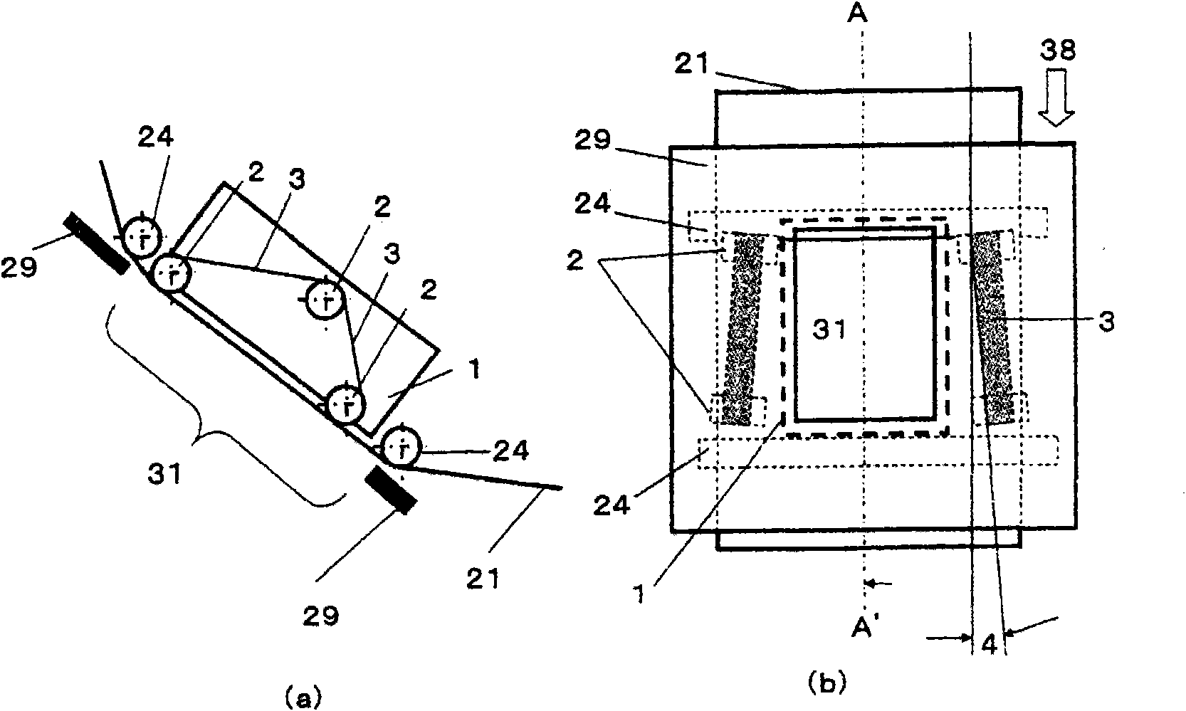
[0090] figure 1 It is a figure which schematically shows the structure of an example of the substrate coolant mechanism which is a part of embodiment of this invention provided with the tension application member in the width direction. figure 1 (a) is the AA' sectional view of (b), figure 1 (b) is from Figure 4 A front view of the film formation source 27 looking at the vicinity of the opening 31 .
[0091] Near both ends in the width direction of the substrate in the vicinity of the opening, along the back surface of the substrate, endless belts 3 held by a plurality of support rollers 2 are in contact with the back surface of the substrate in pairs and rotate (circularly). In addition, the surface of the subject of thin film formation facing the film formation source is defined as the front surface of the substrate, and the opposite surface is defined as the rear surface of the substrate. The width of the annular body 3 is preferably 2 to 50 mm. When the width of the a...
Embodiment approach 2
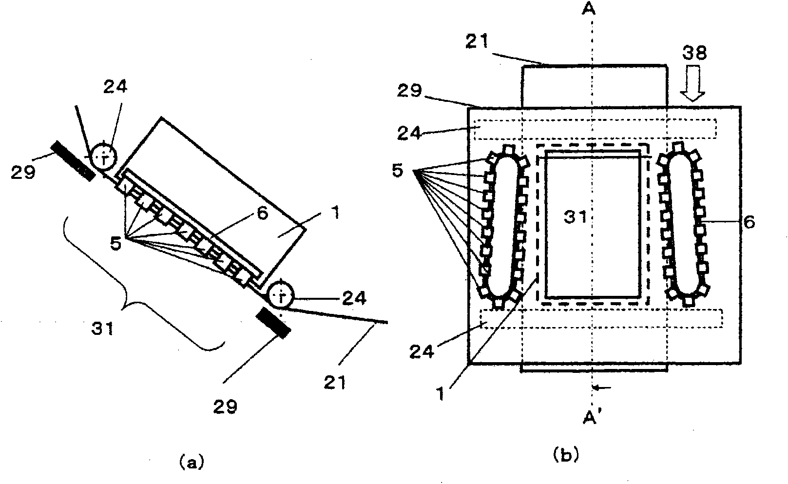
[0098] figure 2 It is a figure which schematically shows the structure of another example of the substrate cooling mechanism which is a part of embodiment of this invention provided with the tension|tensile_strength applying member in the width direction. figure 2 (a) is the AA' sectional view of (b), figure 2 (b) is from Figure 4 A front view of the film formation source 27 looking at the vicinity of the opening 31 .
[0099] Embodiments other than the vicinity of the opening are similar to Embodiment 1, and thus description thereof will be omitted.
[0100] In Embodiment 2, the substrates are successively clamped by the clamp mechanisms 5 arranged at both ends in the width direction of the substrate in the vicinity of the opening. Fixture mechanism such as Figure 9 As in the example shown in the schematic diagram, it has (a) spring type, (b) pneumatic type, (c) electrostatic type, etc. clamping function, and air gap type, spring type, etc. opening function. By oper...
Embodiment approach 3
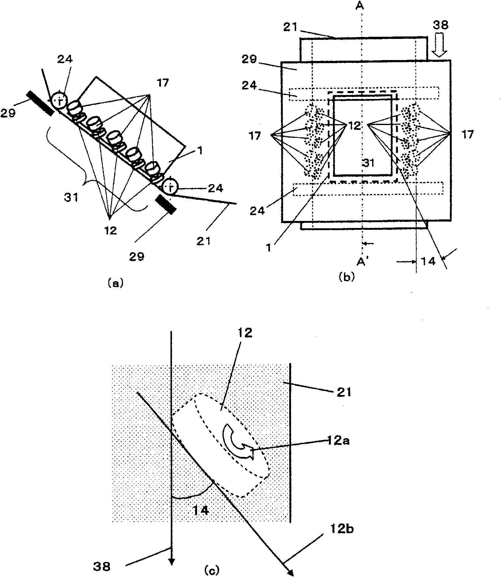
[0104] image 3 It is a figure which schematically shows the structure of another example of the substrate cooling mechanism which is a part of embodiment of this invention provided with the tension|tensile_strength applying member in the width direction. image 3 (a) is the AA' sectional view of (b), image 3 (b) is from Figure 4 The front view of the film forming source 27 watching the vicinity of the opening 31, image 3 (c) is a partially enlarged view of one rotating sliding body located on the right side in (b). but, image 3 In (c), the shielding plate 29 is omitted.
[0105] Embodiments other than the vicinity of the opening are similar to Embodiment 1, and thus description thereof will be omitted.
[0106] In Embodiment 3, tension is applied in the width direction of the substrate to the opening 31 by the rotary sliders 12 disposed near both ends in the width direction of the substrate 21 . The material of the portion of the rotating slider that contacts the su...
PUM
| Property | Measurement | Unit |
|---|---|---|
| width | aaaaa | aaaaa |
Abstract
Description
Claims
Application Information