Cutting pick, cutting pick head and manufacturing method thereof

A manufacturing method and the technology of the pick head, applied in the direction of manufacturing tools, earth drilling, furnace types, etc., can solve the problem of alloy material hardness, insufficient wear resistance, inability to protect the pick main body, picks and pick heads Solve problems such as overall scrapping, and achieve the effect of strong wear resistance, simple structure and extended service life

Inactive Publication Date: 2013-06-12
JIANGYIN CITY YUANFENG HEAT TREATMENT TECH
View PDF0 Cites 0 Cited by
  • Summary
  • Abstract
  • Description
  • Claims
  • Application Information

AI Technical Summary

Problems solved by technology

Its structure is to inlay cylindrical or mushroom head-shaped hard alloy on the top of the pick body. The hard alloy part is called the pick head. After the pick head is used for a period of time, due to the wear of the alloy, it can no longer effectively The main body of the tooth plays a protective role, causing the pick body to be excessively worn. When the alloy on the pick head does not fully function, it will cause the pick head to fall prematurely, resulting in the pick and the pick head being damaged. Whole scrap
At this time, there are still a considerable part of the pick heads that have not been used, resulting in unnecessary waste. The main reason for this phenomenon is that the hardness and wear resistance of the alloy material used in the existing pick heads are not strong enough.

Method used


Image

  • Cutting pick, cutting pick head and manufacturing method thereof

Examples


Embodiment 1

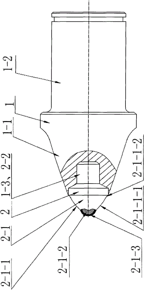
[0020] A pick 1 and a pick head 2. The pick head 2 is welded to the end of the body of the pick 1, and the body of the pick 1 is provided with a tapered section 1-1 and a cylindrical connecting rod section 1-2. One end of the tapered section 1-1 is provided with an axial blind hole 1-3, and the axial blind hole 1-3 is used to connect the pick head 2; the working section 2-1 and the connecting section 2 are provided on the pick head 2 -2, the connecting section 2-2 is inserted into the axial blind hole 1-3. The working section of the pick head 2 is provided with two parts, a conical curved surface section 2-1-1 and a spherical top 2-1-2, and a diamond layer 2-1 is provided on the spherical top 2-1-2 -3. Smooth transitional connection between the diamond layer 2-1-3 and the conical curved surface section 2-1-1.

Embodiment 2

[0022] On the basis of Embodiment 1, a preferred embodiment of the present invention is to control the thickness of the diamond layer 2-1-3 to be between 2 mm and 4 mm, and the rest is completely the same as Embodiment 1.

Embodiment 3

[0024] On the basis of embodiment 2, the preferred embodiment of the present invention is that the conical curved surface section 2-1-1 consists of a convex curved conical section 2-1-1-1 and a concave curved conical section 2-1-1. 2 is composed of two parts, the convex curved conical section 2-1-1-1 and the concave curved conical section 2-1-1-2 smoothly transition, the convex curved conical section 2-1-1 One end is smoothly connected to the diamond layer 2-1-3, and one end of the concave curved conical section 2-1-1 is connected to the connecting section 2-2 on the pick head 2.


PUM

PropertyMeasurementUnit
thicknessaaaaaaaaaa

Abstract

The invention discloses a cutting pick, a cutting pick head and a manufacturing method thereof. The cutting pick head is welded on the end of the cutting pick, and one end of a conical section is provided with an axial blind hole to be connected with the cutting pick head; the cutting pick head is provided with a working section and a connecting section, and the connecting section is spliced in the axial blind hole; and the working section of the cutting pick head is provided with a conical camber section and a spherical top end, the spherical top end is provided with a diamond layer, and thediamond layer and the conical camber section are connected through smooth transition. The manufacturing method of the cutting pick and the cutting pick head comprises the following steps: die-castingsintered carbide into a shape of a cutting pick head with a die; compounding diamond powder on the surface of the spherical top end of the cutting pick head through die pressing under high temperature and high pressure; carrying out thermal treatment of the processed cutting pick head; and welding the cutting pick head and the cutting pick body with a welding machine. The cutting pick and the cutting pick head have the advantages of simple structure, high hardness and high wear resistance, and the service lives thereof can be prolonged significantly.

Description

Technical field [0001] The invention relates to a mining machine tool, in particular to a mining machine and a cutting tool on an excavator. Background technique [0002] Conical picks, also known as cutting tools, are mainly used for ore mining and coal mining operations of construction machinery. Its structure is to inlay a cylindrical or mushroom-shaped cemented carbide on the top of the pick body. The cemented carbide part is called the pick head. After the pick head is used for a period of time, it can no longer be effectively cut due to the wear of the alloy. The tooth body plays a protective role, causing the pick body to be excessively worn. If the alloy on the pick head is not fully functional, it will cause the pick head to fall prematurely, causing the pick and the pick head to fail. The whole is scrapped. At this time, a considerable part of the pick head is still unused, causing unnecessary waste. The main reason for this phenomenon is that the hardness and wear re...

Claims


Application Information

Patent Timeline
Patent Type & Authority Patents(China)
IPC IPC(8): E21C35/183B22F3/16C21D9/00
Inventor 朱惠忠
Owner JIANGYIN CITY YUANFENG HEAT TREATMENT TECH
Why Eureka
Try Eureka