Rotary laser visual linear array space identification and positioning system

A laser line and rotary technology, applied in the field of rotary laser vision linear array space identification and positioning system, can solve the problems of complex processing technology, unable to expand the scanning range, effective distance limitation, etc. Simple, wide-ranging effects

Inactive Publication Date: 2010-10-06
崔一 +1
View PDF6 Cites 19 Cited by
  • Summary
  • Abstract
  • Description
  • Claims
  • Application Information

AI Technical Summary

Problems solved by technology

[0003] 1. Low spatial positioning accuracy: Due to the use of area array scanning, the pixels of the area array are used to determine the resolution of the target object to be measured. Due to the complicated processing technology, the effective pixel of the area array is 1280×1024. Obviously, it is no longer possible Satisfying high-precision spatial positioning, it is generally difficult to measure at a distance of more than 5 meters for multi-eye visual imaging;
[0004] 2. There are limitations in the scanning range: the current methods are all designed based on the area array. Since the effective pixels of the area array are fixed, the scanning range can no longer be expanded under the premise of ensuring the scanning accuracy;
[0005] 3. Poor environmental adaptability: Based on multi-eye vision imaging technology, changes in environmental light source and scanning distance have a greater impact on spatial positioning, and the effective distance is also limited;
[0006] 4. Poor color synthesis and mixed recognition ability in spatial position: 3D scanners use the linear propagation of laser and the principle of laser ranging for spatial positioning, and the feedback does not contain color information. It is difficult to achieve color by a single technology of laser array or CCD array It is even more impossible to combine three-dimensional space recognition and two-dimensional image recognition to improve the accuracy of recognition;

Method used


Image

  • Rotary laser visual linear array space identification and positioning system
  • Rotary laser visual linear array space identification and positioning system
  • Rotary laser visual linear array space identification and positioning system

Examples


Embodiment Construction

[0039] Attached below Figure 4 The rotary laser vision linear array space recognition and positioning system is further described, and the specific implementation steps are as follows:

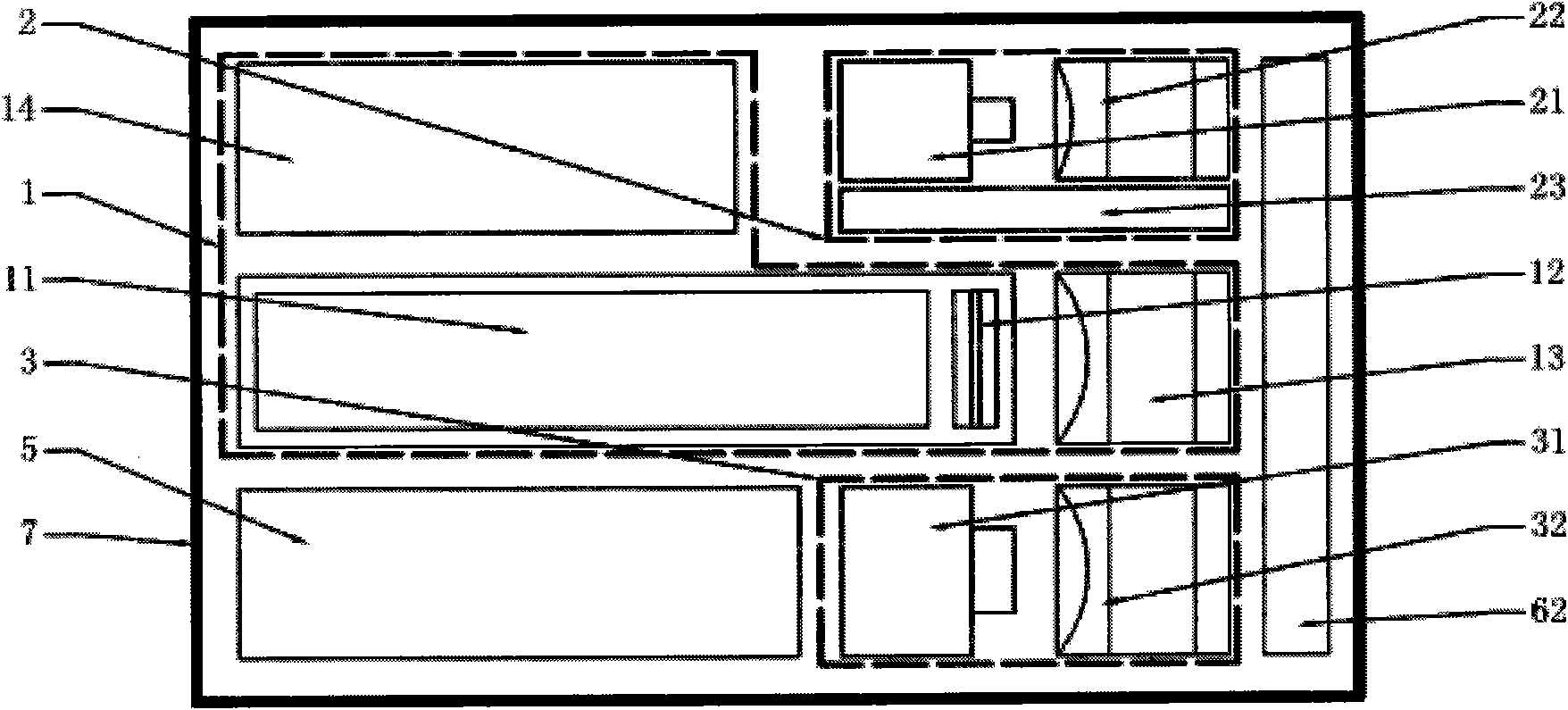
[0040] The first step: preparation work, adjust each lens group (12, 22, 32) to determine the best viewing range of the scanning target 8 longitudinal line array, determine the initial scanning origin position, input the rotation scanning angle a and the scanning precision subdivision n ;

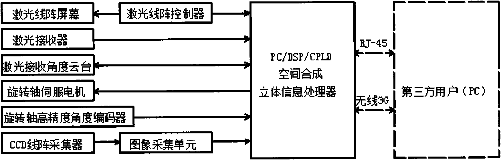
[0041] The second step: the laser line array 1 scans the distance point by point, calculates the three-dimensional coordinate position in space according to the initial scanning origin position, the CCD line array 3 scans to obtain color information, and stores the obtained information data into the three-dimensional information processor 5 database;

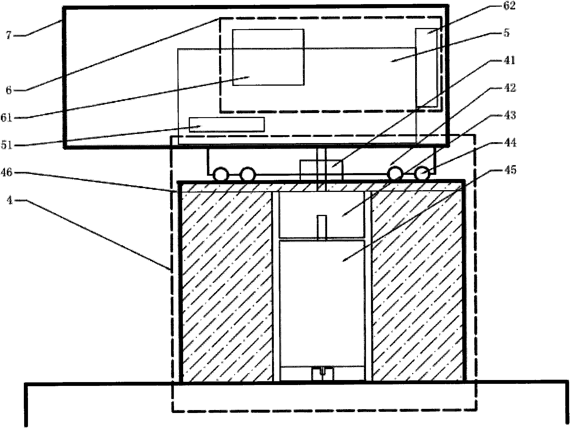
[0042] Step 3: Wait for the linear array scanning to be completed, the servo motor 45 rotates the subdivision angle a b / n (n is the subdivision of the pres...


PUM


Abstract

The invention relates to a rotary laser visual linear array space identification and positioning system, which belongs to the field of mode identification and artificial intelligence. The system comprises a laser linear array emission module, a holder laser-receiving module, a CCD linear array acquisition module, a principal-axis rotation module, a three-dimensional information processor and an auxiliary module. The laser linear array is used for ranging, the CCD linear array is used for acquiring colors, the high-subdivision principal-axis rotation module is used for carrying out 360-degree rotary scanning to acquire high-precision three-dimensional position data and two-dimensional color images, the three-dimensional information processor is used for synthesizing the three-dimensional position and color data (X, Y, Z, RGB) of all the pixel points in the rotating space, and the synthesized data can be directly used for mixing identification and intelligence applications, or can be outputted to a third-party user via RJ45 or wireless 3G. The system is characterized by high precision, wide scanning range, high environment adaptability, wide application range, simple implementation technique and the like.

Description

Technical field: [0001] The invention relates to a rotary laser vision linear array space recognition and positioning system, which belongs to the field of pattern recognition and artificial intelligence, and is used for high-speed and accurate acquisition of three-dimensional position color data of a target object. Background technique: [0002] At present, spatial recognition and positioning are widely used in the fields of pattern recognition, high-precision detection, automation and artificial intelligence, and play a pivotal role in the development of the industry. Most of the current spatial positioning uses area array 3D scanners or multi-eye vision imaging as the main means to obtain the 3D position data of the target object. The common method is to place the scanner at a specific position, adjust the ambient light source and scanning distance to ensure The target object is within the viewing range, and this method has the following defects: [0003] 1. Low spatial ...

Claims


Application Information

Patent Timeline
Patent Type & Authority Applications(China)
IPC IPC(8): G01C11/00G01C3/00
Inventor 崔一石建华
Owner 崔一
Why Eureka
Try Eureka