Optical mode cleaner

A cleaner and optical mode technology, applied in lasers, laser parts, laser parts, etc., can solve the problems of cavity temperature control and stability need to be further improved, and achieve the effect of reducing deformation

Inactive Publication Date: 2010-10-06
SHANXI UNIV
2 Cites 4 Cited by

AI-Extracted Technical Summary

Problems solved by technology

This mold cleaner adopts an integral cavity structure, but the overall temperature co...

Abstract

The invention provides an optical mode cleaner, which comprises a three-mirror ring optical resonance cavity. The three-mirror ring optical resonance cavity comprises a cylindrical cavity (1), a pyrometric cone (5) and a circular bottom plate (10). One end of the cylindrical cavity (1) is connected with the pyrometric cone (5) and the other end of the cylindrical cavity (1) is connected with the circular bottom plate (10) to form a sealed integral cavity. A plane mirror (6) and a plane mirror (7) are respectively fixed on two inclined surfaces of the pyrometric cone (5). A concave mirror (8) and piezoelectric ceramics (9) are fixed in the center of the circular bottom plate (10). The resonance cavity is made of invar steel, a temperature control device is used for integrally controlling the temperature of the cavity, the entire cavity is sealed and the cavity is fixed on a V-shaped base in a way of line contact. The optical mode cleaner has high stability and narrow line width and can be used in aspects such as filtering extra noise of laser, improving light spot quality, improving the compression degree or entanglement degree of nonclassical optical fields, and the like.

Application Domain

Laser cooling arrangements

Technology Topic

PhysicsLine width +6

Image

  • Optical mode cleaner
  • Optical mode cleaner
  • Optical mode cleaner

Examples

  • Experimental program(1)

Example Embodiment

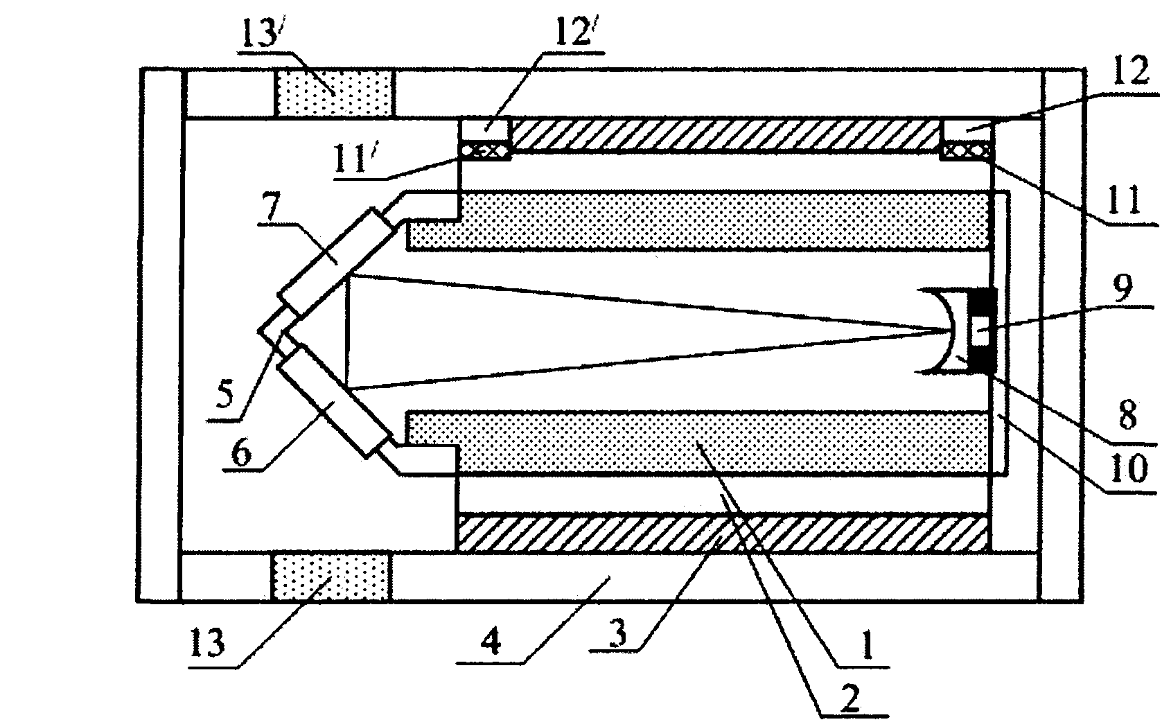
[0020] An embodiment of the present invention, such as figure 1 As shown, the three-mirror ring optical resonant cavity includes a cylindrical cavity 1, a triangular cone 5 and a circular bottom plate 10. The cylindrical cavity 1 is an Invar cylinder with an inner diameter of 25mm and an outer diameter of 40mm. One end of the body 1 is tightly connected with the cone 5, and the other end is fixed with the circular bottom plate 10 by screws. Indium foil is added to the contact surface to adjust the light closure in the optical cavity to form a sealed integral cavity. The plane mirrors 6 and 7 are respectively fixed on the two slopes of the cone 5. The concave mirror 8 and the piezoelectric ceramic 9 are fixed on the center of the circular base plate 10; the reflectivity of the plane mirrors 6 and 7 is 99.7%, and the reflection of the concave mirror 8 The rate is 99.95%; the flat mirrors 6 and 7 choose flat mirrors with a diameter of 25 mm, and the concave mirror 8 chooses a concave mirror with a radius of curvature of 1 m and a diameter of less than 10 mm, and bonds them on the piezoelectric ceramic. The length of the three-mirror ring optical cavity is 520mm, the optical path between the two flat mirrors is 20mm, and the optical path between the flat mirror and the concave mirror is 250mm. The temperature control sleeve 2 tightly wraps the cylindrical cavity 1, the heat insulation sleeve 3 tightly wraps the temperature control sleeve 2, and the two ends of the temperature control sleeve 2 are respectively placed with a 20×20mm 2 The semiconductor refrigeration devices 11 and 11' are pressed and fixed with small copper blocks 12 and 12'; the shell 4 tightly wraps the heat insulation sleeve 3, and seals the entire three-mirror ring optical resonant cavity with sealant; the shell 4 corresponds to the plane mirror Light-through holes 13 and 13' are provided at positions 6 and 7, and anti-reflective film-plated windows are fixed on the light-through holes 13 and 13' to ensure the passage of light. The shell 4 is fixed on a V-shaped base 14 by wire contact (e.g. figure 2 Shown). The cylindrical cavity 1, the triangular cone 5, and the circular bottom plate 10 of the three-mirror ring optical resonant cavity are made of Invar material with a small thermal expansion coefficient; the temperature control sleeve 2 is made of a high thermal conductivity It is made of red copper material; the heat insulation cover 3 is made of heat preservation material. The optical mold cleaner has a fineness of 1000 for s-polarized light, a line width of 600 kHz, and a fineness of 200 for p-polarized light and a line width of 3 MHz. If you want to obtain an optical mold cleaner with higher fineness and narrower line width, you can choose optical lenses with higher reflectivity and longer cavity lengths.
[0021] In order to control the temperature of the optical mold cleaner, for optical mold cleaners with different cavity lengths, different numbers of semiconductor refrigeration devices and different placement methods should be selected. When the cavity length is short, you only need to place a semiconductor refrigeration device at each end (such as figure 1 As shown); when the cavity length is longer, a larger number of semiconductor refrigeration devices are required to effectively control the temperature of the three-mirror ring optical resonant cavity. Placement method such as image 3 As shown, that is, another embodiment of the present invention, at both ends of the temperature control sleeve 2, two 20×20mm are placed side by side. 2 The semiconductor refrigeration devices 11, 11' and 11", 11", and use 20×40mm 2 The small copper blocks 12 and 12' are pressed and fixed. The rest and figure 1 The structure in is the same.
[0022] The above optical mold cleaner can be applied to filter the extra noise of the laser, improve the quality of the spot, and increase the degree of compression or entanglement of the non-classical light field.

PUM

no PUM

Description & Claims & Application Information

We can also present the details of the Description, Claims and Application information to help users get a comprehensive understanding of the technical details of the patent, such as background art, summary of invention, brief description of drawings, description of embodiments, and other original content. On the other hand, users can also determine the specific scope of protection of the technology through the list of claims; as well as understand the changes in the life cycle of the technology with the presentation of the patent timeline. Login to view more.

Similar technology patents

Classification and recommendation of technical efficacy words

  • reduce deformation

Rotating needle driver and apparatuses and methods related thereto

ActiveUS20100234856A1reduce insertion forcereduce deformation
Owner:THE JOHN HOPKINS UNIV SCHOOL OF MEDICINE

Alkaline cell with flat housing and nickel oxyhydroxide cathode

ActiveUS7435395B2reduce deformationless gas
Owner:DURACELL U S OPERATIONS

Friction stir weld tool and method

ActiveUS20050121497A1increase mixingreduce deformation
Owner:THE BOEING CO

Flexible displaying device

Owner:WUHAN CHINA STAR OPTOELECTRONICS SEMICON DISPLAY TECH CO LTD
Why Eureka
Try Eureka