Force-electricity energy converter and array thereof

A transducer array and transducer technology, applied in the direction of electrical components, generators/motors, piezoelectric effect/electrostrictive or magnetostrictive motors, etc., can solve the problem of low piezoelectric performance and cannot withstand large Pressure, high resonance frequency and other problems, to achieve the effect of reducing resonance frequency, large energy output, and long working life

Inactive Publication Date: 2010-10-06
PEKING UNIV
View PDF3 Cites 11 Cited by
  • Summary
  • Abstract
  • Description
  • Claims
  • Application Information

AI Technical Summary

Problems solved by technology

The cantilever beam force-electric transducer is suitable for low-frequency, small-amplitude mechanical vibration energy recovery, and cannot withstand high pressure; the piezoelectric / metal "cymbal" composite structure is an improved version of the cantilever beam force-electric transducer, but due to Working in the bending-tension mode, under the action of large tension, piezoelectric ceramics or piezoelectric single crystal elements with brittle characteristics are easily damaged; although piezoelectric cylindrical or disc-shaped force-electric transducers can withstand large Positive pressure, but due to its high stiffness resulting in a very high resonant frequency, not suitable for low frequency vibration mechanical energy recovery
Flexible piezoelectric polymer film structure force-electric transducer can work at low frequency and withstand relatively high pressure, but its piezoelectric performance is far lower than that of piezoelectric ceramics and piezoelectric single crystals

Method used


Image

  • Force-electricity energy converter and array thereof
  • Force-electricity energy converter and array thereof
  • Force-electricity energy converter and array thereof

Examples


Embodiment Construction

[0017] The present invention will be further described below in conjunction with specific embodiments.

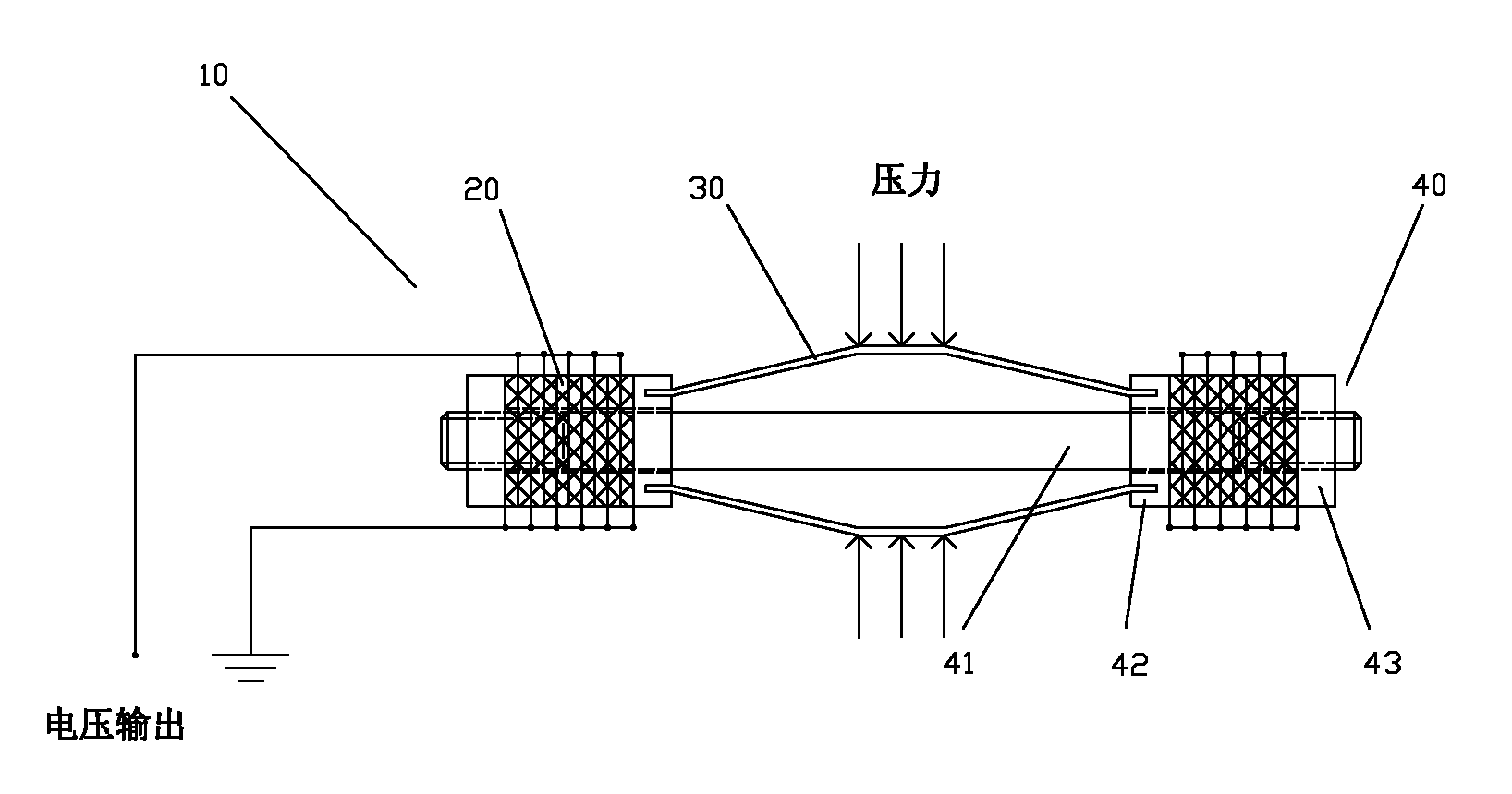
[0018] Depend on figure 1 It can be seen that the shown force-electric transducer unit 10 includes a pair of piezoelectric stacks 20 with a central inner hole, a pair of slightly arched elastic elements 30 placed between the two piezoelectric stacks, and A pretensioning device 40 for assembling the piezoelectric stack 20 and the elastic element 30 .

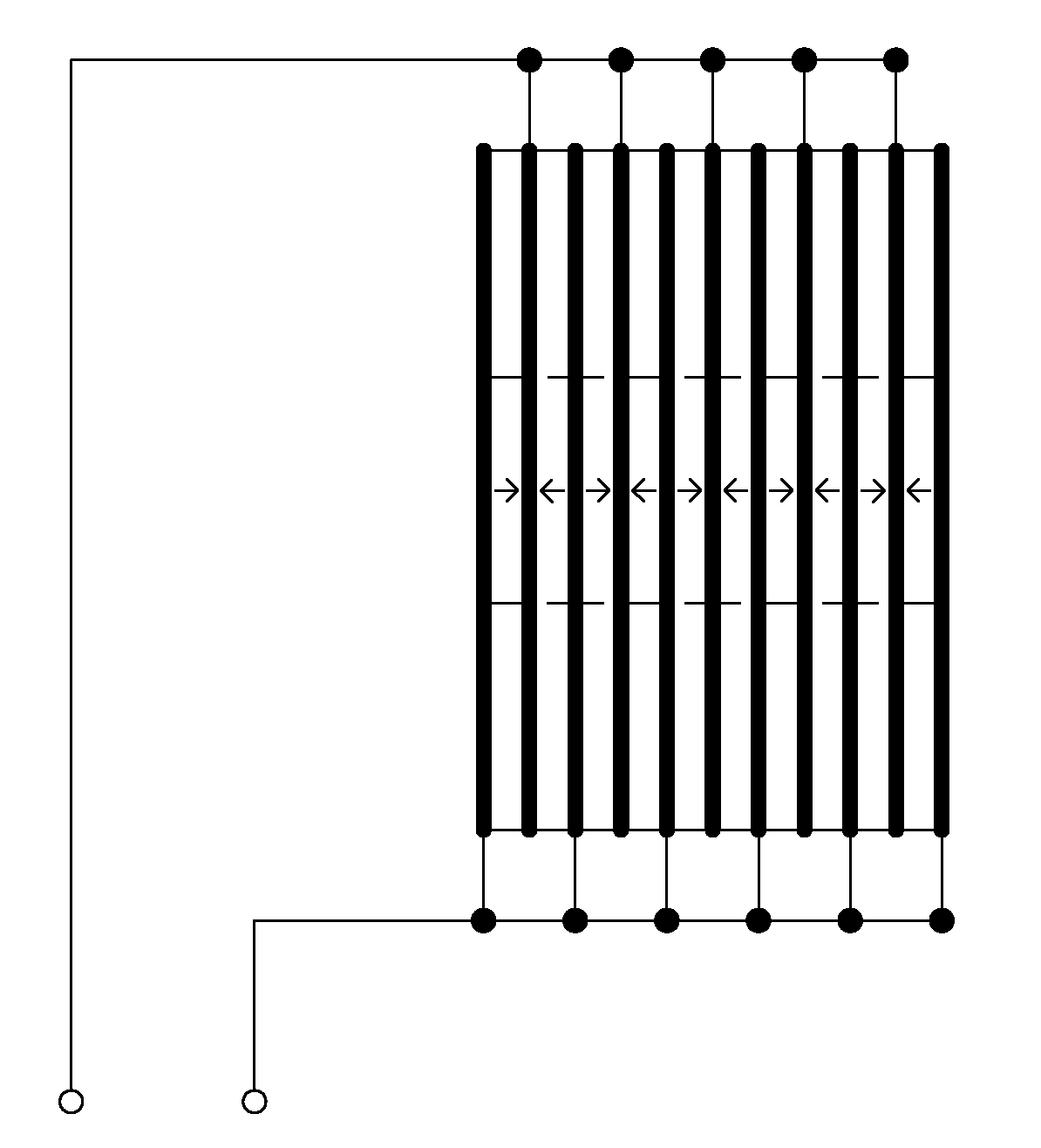
[0019] figure 2 for figure 1 A schematic structural diagram of the piezoelectric stack 20 of the force-electric transducer 10 is shown. The piezoelectric stack 20 can be composed of multiple annular piezoelectric ceramic sheets or piezoelectric single crystals and thin copper sheets (adhesively bonded by epoxy resin) in the axial direction, or can be prepared by electrode-ceramic co-sintering method multilayer piezoelectric ceramics; the piezoelectric element in the piezoelectric stack 20 is preferably an even number, pol...


PUM


Abstract

The invention discloses a force-electricity energy converter and an array thereof. The energy converter works in a bending-pressing mode and converts vibration of an environment or energy generated when a human body walks into electric energy by using a piezoelectricity principle. The energy converter of the invention comprises a pair of piezoelectric units and a pair of bow-shaped elastic elements, wherein the piezoelectric units and the elastic elements are fixed by pre-loading devices; and the elastic elements convert a transverse force (or outside vibration) applied by the outside to an elastic strip into longitudinal (axial) pressure which is applied to the piezoelectric units and is amplified in the bending-pressing mode and then the piezoelectric units efficiently generate electricity through the piezoelectric effect. The invention further relates to the array of the force-electricity energy converter. The array is used for converting mechanical energy which is generated when the human body (including other moving vehicles) operates on a plate into the electric energy and outputting the electric energy. The force-electricity energy converter and the array thereof have the advantages of simple structure, low resonant frequency and low manufacturing cost and can guarantee to work for a long term under the high-pressure working condition.

Description

technical field [0001] The invention belongs to the field of mechanical energy recovery and power generation, in particular to a force-electric transducer. Background technique [0002] In today's world, with the increasing depletion of non-renewable energy sources, environmental energy recovery and power generation have increasingly become a topic of concern to scientists from all over the world. More and more scientists have devoted themselves to the research of environmental energy recovery and power generation devices, including environmental Various forms of energy recovery devices have been developed for the recovery and power generation of light energy, thermal energy, electromagnetic energy, mechanical and vibration energy. The piezoelectric energy recovery device directly converts mechanical energy into electrical energy output through the piezoelectric effect of a force-electric transducer. Compared with electromagnetic energy recovery devices, it has obvious advan...

Claims


Application Information

Patent Timeline
Patent Type & Authority Applications(China)
IPC IPC(8): H02N2/18
Inventor 董蜀湘李晓天郭明森
Owner PEKING UNIV
Why Eureka
Try Eureka