Dual-rate optical signal receiving device

A receiving device and dual-rate technology, applied in the field of optical communication, can solve the problems of increasing system cost and complexity, loss of optical path power, and violation of communication network layering, etc.

Active Publication Date: 2010-10-06
CHENGDU SUPERXON COMM TECH CO LTD
View PDF4 Cites 19 Cited by
  • Summary
  • Abstract
  • Description
  • Claims
  • Application Information

AI Technical Summary

Problems solved by technology

[0005] For the first solution, the advantage is that the two optical signals can be processed by subsequent circuits with different rates, and the disadvantage is that the optical splitter will cause power loss on the optical path, thereby reducing the receiving sensitivity of the two paths
The way to improve it is to add an optical amplifier in the rear stage of the splitter, but the optical path is complicated, and it is difficult to meet the requirements of module miniaturization, which further increases the cost and complexity of the system
[0006] For the second solution, the advantage is that only a set of photodetectors and transimpedance amplifiers are needed. The disadvantage is that if it is a fixed bandwidth photodetector and transimpedance amplifier, it is difficult to optimize

Method used


Image

  • Dual-rate optical signal receiving device
  • Dual-rate optical signal receiving device
  • Dual-rate optical signal receiving device

Examples


Embodiment Construction

[0024] The technical solutions of the present invention will be further described below in conjunction with the accompanying drawings and through specific implementation methods.

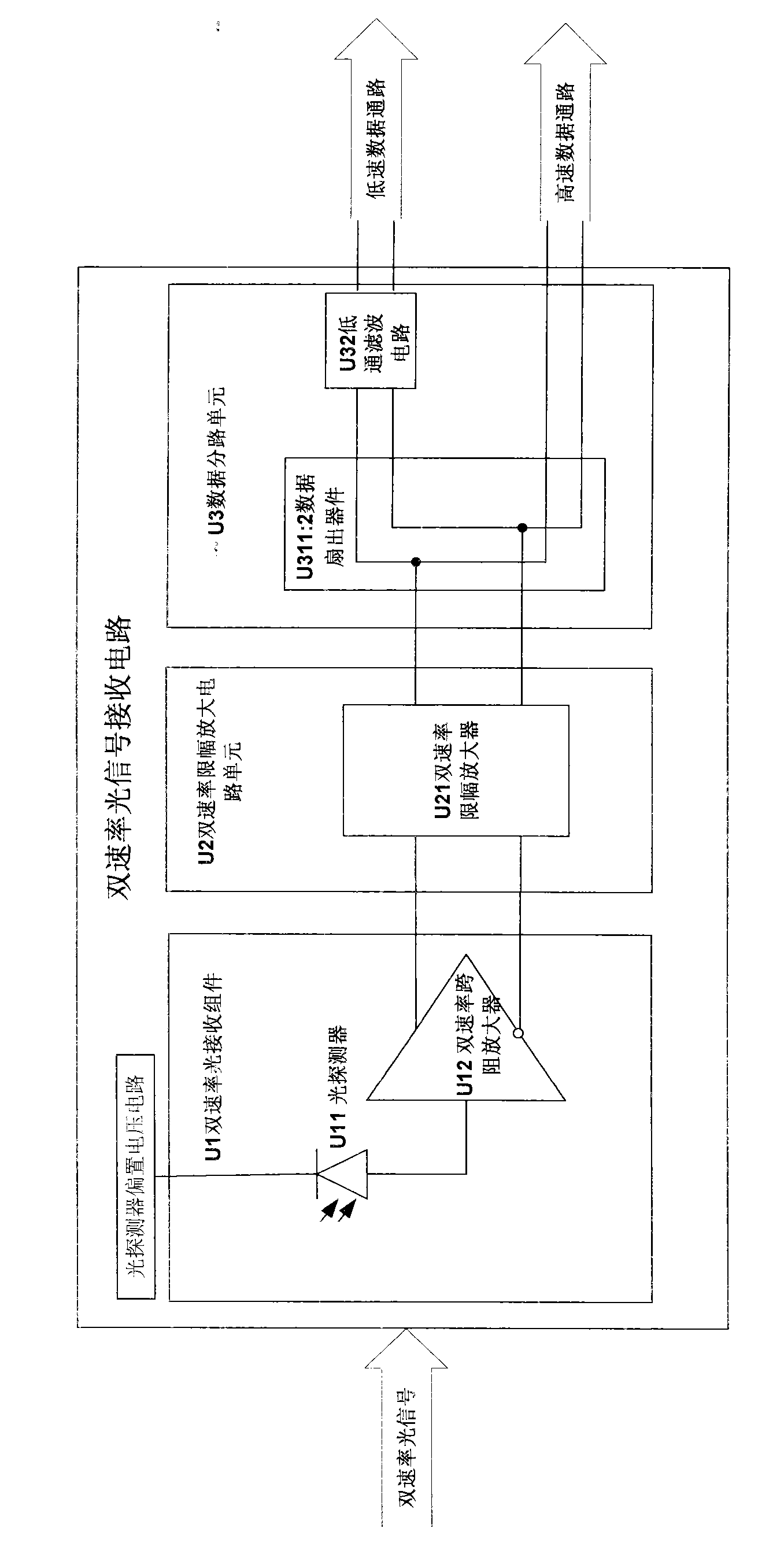
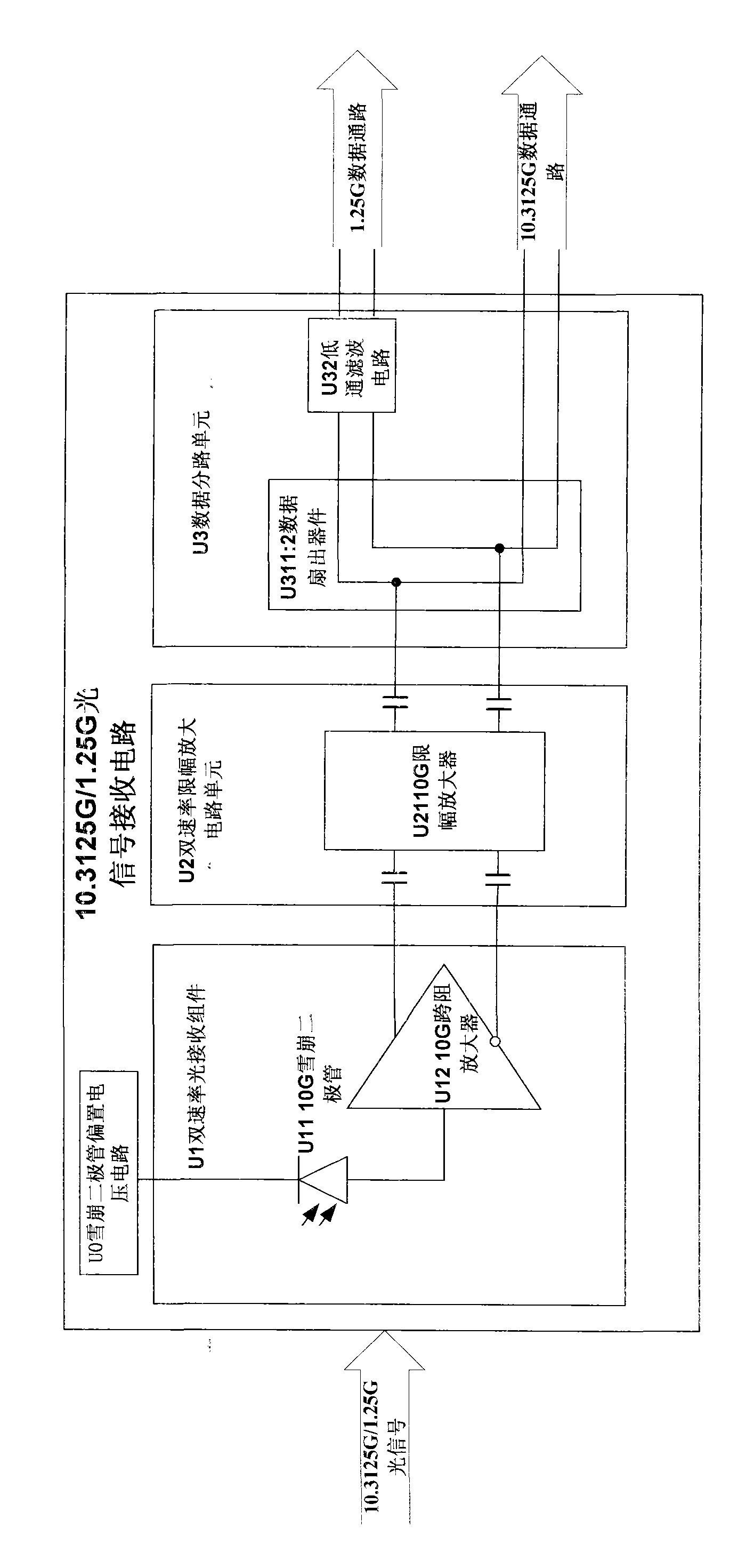
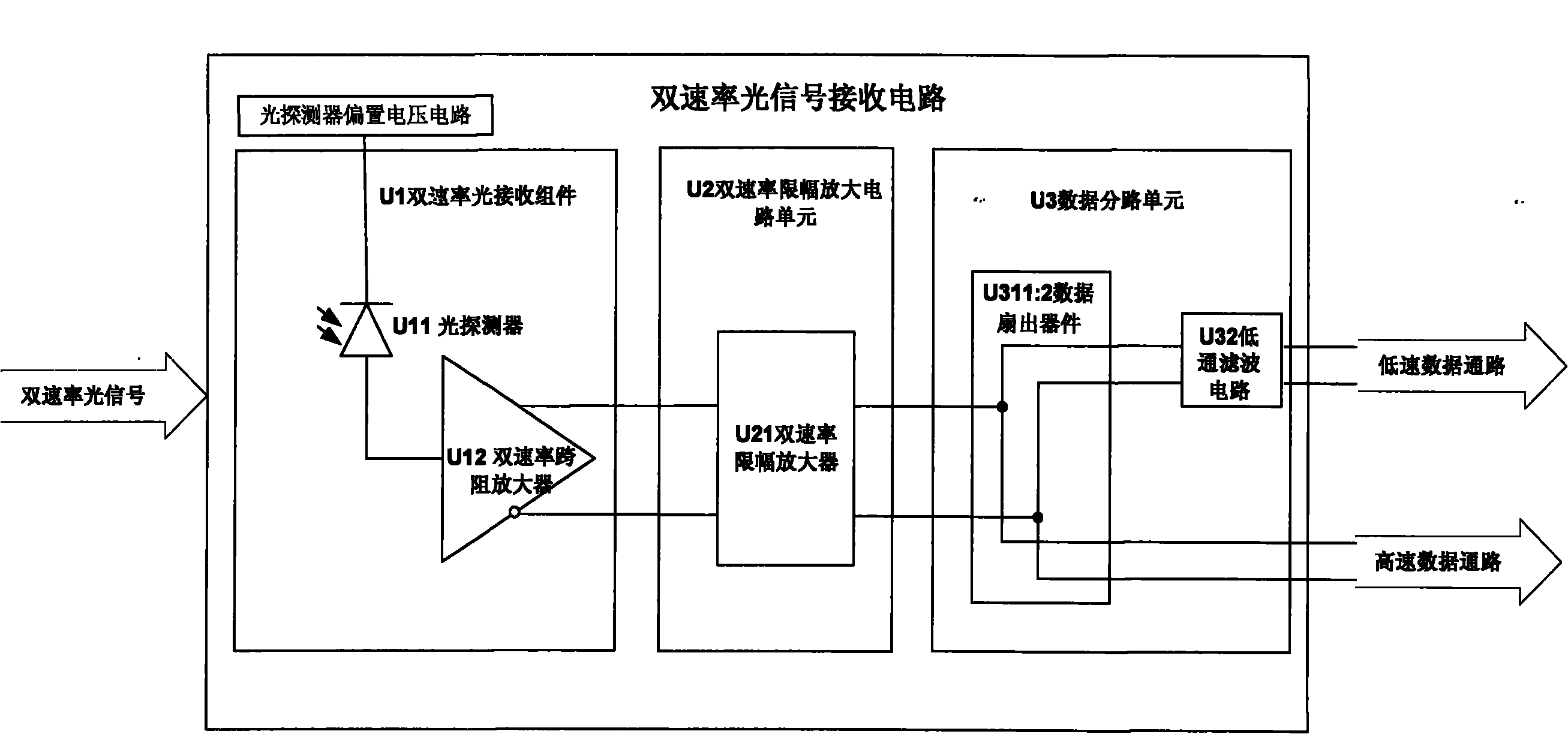
[0025] figure 1 It is a schematic structural diagram of a dual-rate optical signal receiving device of the present invention. Such as figure 1 As shown, the dual-rate optical signal receiving device is a dual-rate optical signal receiving circuit, including U1 dual-rate optical receiving component, U2 dual-rate limiting amplifier circuit unit and U3 data branching unit, and the dual-rate optical receiving component further includes U11 optical The detector and U12 dual-rate transimpedance amplifier, the dual-rate limiting amplifying circuit unit further includes a U21 dual-rate limiting amplifier, and the data branching unit further includes a U311 ratio 2 data fan-out device and a U32 low-pass filter circuit.

[0026] The dual-rate optical receiving component and the dual-rate limiting amplifier ...


PUM


Abstract

The invention discloses a dual-rate optical signal receiving device, which comprises a dual-rate optical receiving component, a dual-rate limiting amplifier circuit unit, and a data shunt unit. The dual-rate optical receiving component also comprises an optical detector and a dual-rate transimpedance amplifier; the dual-rate limiting amplifier circuit unit also comprises a dual-rate limiting amplifier; and the data shunt unit also comprises a 1:2 data fan-out device and a low-pass filter circuit. Due to the adoption of the technical scheme, through two optical signal receiving circuits formed by time division multiplexing on data at different rates, the received data is divided into two data channels at different rates through a data shunt device. Therefore, an easily realized physical layer solution is provided for the dual-rate time division multiplexed data.

Description

technical field [0001] The invention relates to the technical field of optical communication, in particular to a dual-rate optical signal receiving device. Background technique [0002] Optical communication devices usually work at multiple operating rates, which requires optical communication physical layer circuits to be able to work at multiple rates, which brings difficulties to actual circuit design. [0003] This contradiction is particularly prominent in the dual-rate receiver in the photoelectric module of the optical line terminal of the 10 Gigabit Ethernet passive optical network. In order to be compatible with the existing Gigabit Ethernet passive optical network unit equipment, the 10 Gigabit Ethernet passive optical The optical receiving circuit of the optical transceiver module of the network optical line terminal needs to be able to receive optical signals of 10.3125Gbps and 1.25Gbps data through time division multiplexing. [0004] Institute of Electrical an...

Claims


Application Information

Patent Timeline
IPC IPC(8): H04B10/148H04B10/158H04B10/60
Inventor 董轲蔺敬平
Owner CHENGDU SUPERXON COMM TECH CO LTD
Why Eureka
Try Eureka