Improved structural sandwich plate panels and methods of making the same

A sandwich panel and component technology, applied in the field of ships, offshore structures and buildings, can solve the problems of low thermal conductivity of concrete slabs

Inactive Publication Date: 2010-10-06
INTELLIGENT ENG BAHAMAS
View PDF7 Cites 6 Cited by
  • Summary
  • Abstract
  • Description
  • Claims
  • Application Information

AI Technical Summary

Problems solved by technology

However, due to the high thermal mass and low thermal conductivity of concrete sl...

Method used


Image

  • Improved structural sandwich plate panels and methods of making the same
  • Improved structural sandwich plate panels and methods of making the same
  • Improved structural sandwich plate panels and methods of making the same

Examples


Embodiment Construction

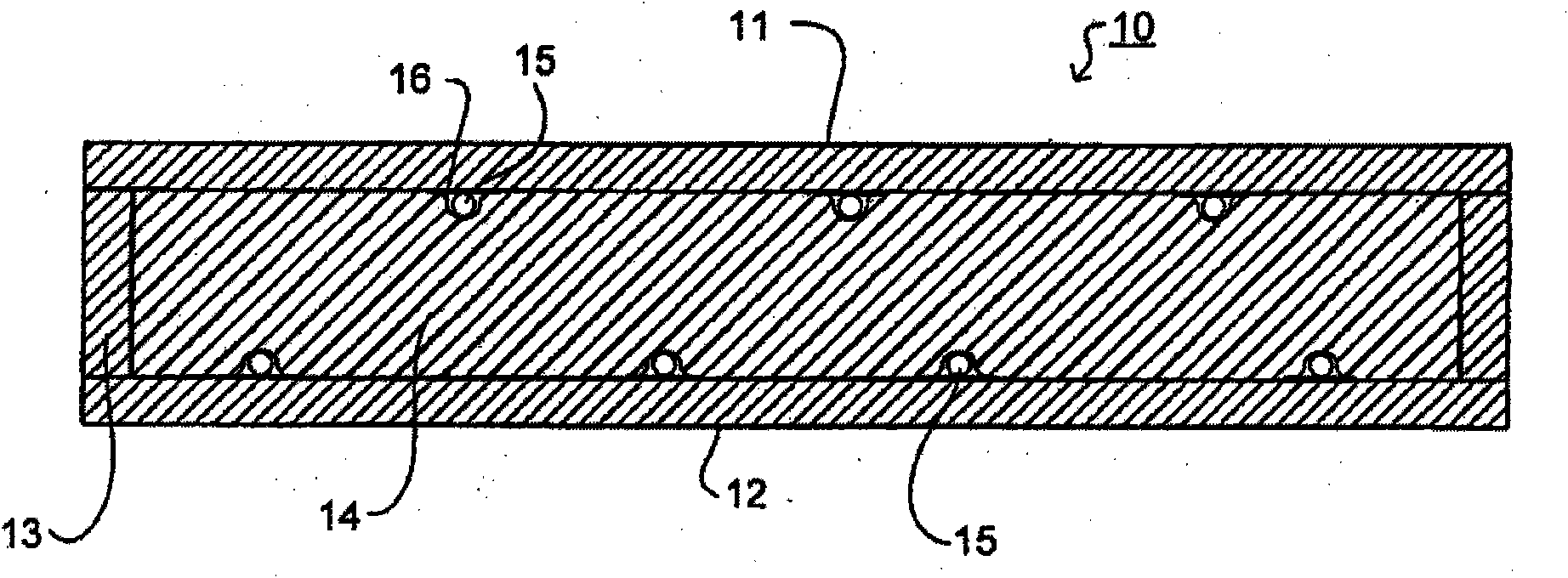
[0023] exist figure 1 The structural sandwich panel members (or panels) shown in include upper and lower outer panels (panels) 11, 12, which may be made of steel, aluminum or other metals, and have For example a thickness in the range of 0.5 to 8 mm, preferably a thickness in the range of 1 to 5 mm, more preferably a thickness in the range of 1 to 2.5 mm. Between the panels 11 , 12 there is provided a side panel, a crimped configuration, an extruded configuration or a strip 13 around its periphery to form a closed cavity. In the cavity between the panels 11 , 12 is a core 14 . The core may have a thickness in the range of 15 to 200mm; in many applications 25 to 100mm is suitable. The overall dimensions of the plate member in plan may be 1 to 5 m wide by 5 to 15 m long. Preferred dimensions are 2.5m by 10m. Plate members may be made to standard sizes or custom made to specific shapes and / or sizes.

[0024] The core 14 comprises a plastic or polymer material (preferably a t...


PUM


Abstract

The present application relates to a structural sandwich plate member comprising first and second outer metal plates and a core of plastics or polymer material bonded to the outer metal plates and arranged to transfer shear forces there between, wherein the member further comprises: a conduit for a temperature control medium, the conduit being embedded in the core and in thermal contact with at least one of the outer metal plates.

Description

technical field [0001] This invention relates to structural sandwich panels, particularly for ships, offshore structures and buildings. Background technique [0002] Marine applications place high demands on the HVAC system in order to provide a high indoor climate regardless of the climatic zone in which the ship operates. The most commonly used is the forced convection air conditioning system, which controls the temperature of the room by supplying cool or warm air. Various tailor-made fans, piping and air moving devices, air handling units with automation and control systems are installed in spaces on ships and platforms to provide an indoor climate meeting the required standards, for example with reference to BS EN ISO 7730: 1995, "Moderate thermal environments. Determination of the PMV and PPD indices and specification of the conditions for thermal comfort" Such systems are costly in terms of materials, work required for installation and saving available free space. ...

Claims


Application Information

Patent Timeline
IPC IPC(8): B32B3/20B32B15/06B32B15/08E04C2/34F28D1/04F28D1/047F28D21/00F28F1/22F28F3/12
CPCE04C2/525F28F21/067F28F2275/02B32B15/06E04C2/292F28D1/0477F28F1/22B63B3/68Y10T156/10B32B15/08B63B3/14F24D3/142F24D13/022F25D23/061F25D23/063
Inventor 欧列格·苏库沃伊
Owner INTELLIGENT ENG BAHAMAS
Why Eureka
Try Eureka