Eureka AIR delivers breakthrough ideas for toughest innovation challenges, trusted by R&D personnel around the world.

Low-permeation flexible fuel hose

A hose and flexible technology, applied in the field of flexible fuel hoses, can solve problems such as the flexibility of hose applications that have not been discussed

Inactive Publication Date: 2010-10-06
THE GATES CORP
View PDF7 Cites 4 Cited by
  • Summary
  • Abstract
  • Description
  • Claims
  • Application Information

AI Technical Summary

Problems solved by technology

No discussion of flexibility in hose applications

Method used


Image

  • Low-permeation flexible fuel hose
  • Low-permeation flexible fuel hose
  • Low-permeation flexible fuel hose

Examples


Embodiment Construction

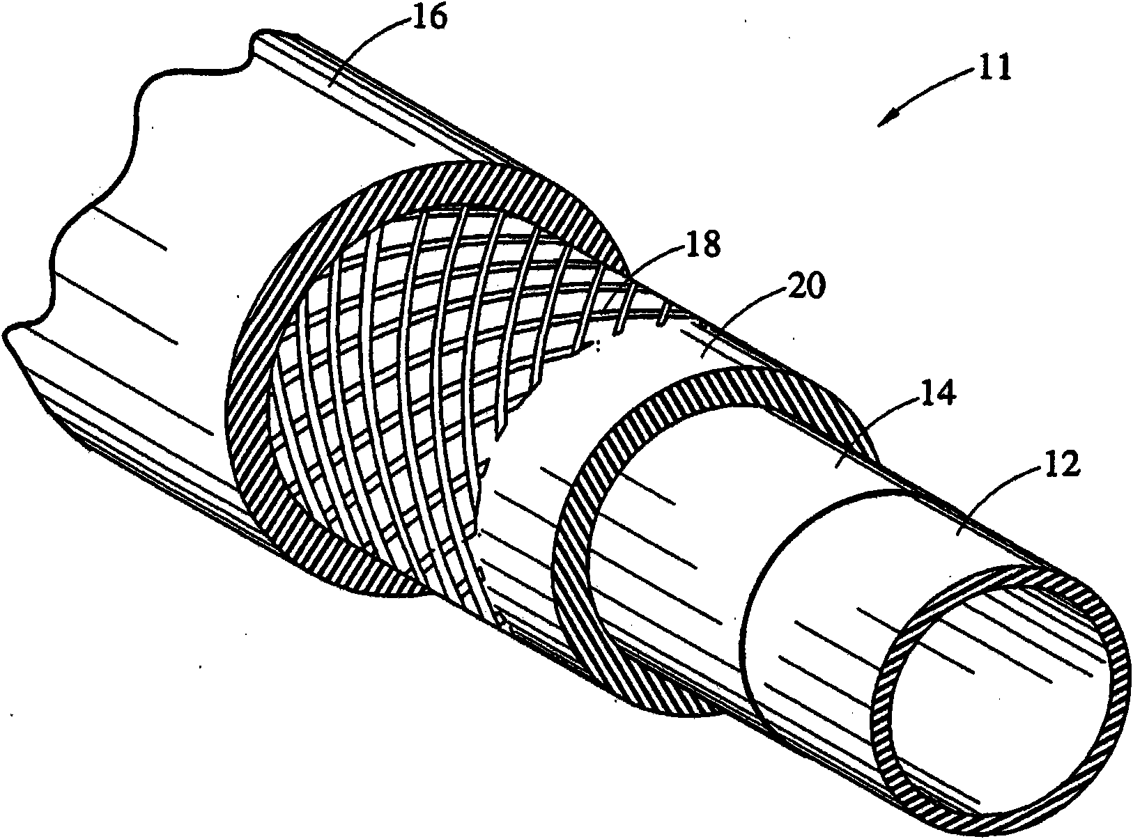
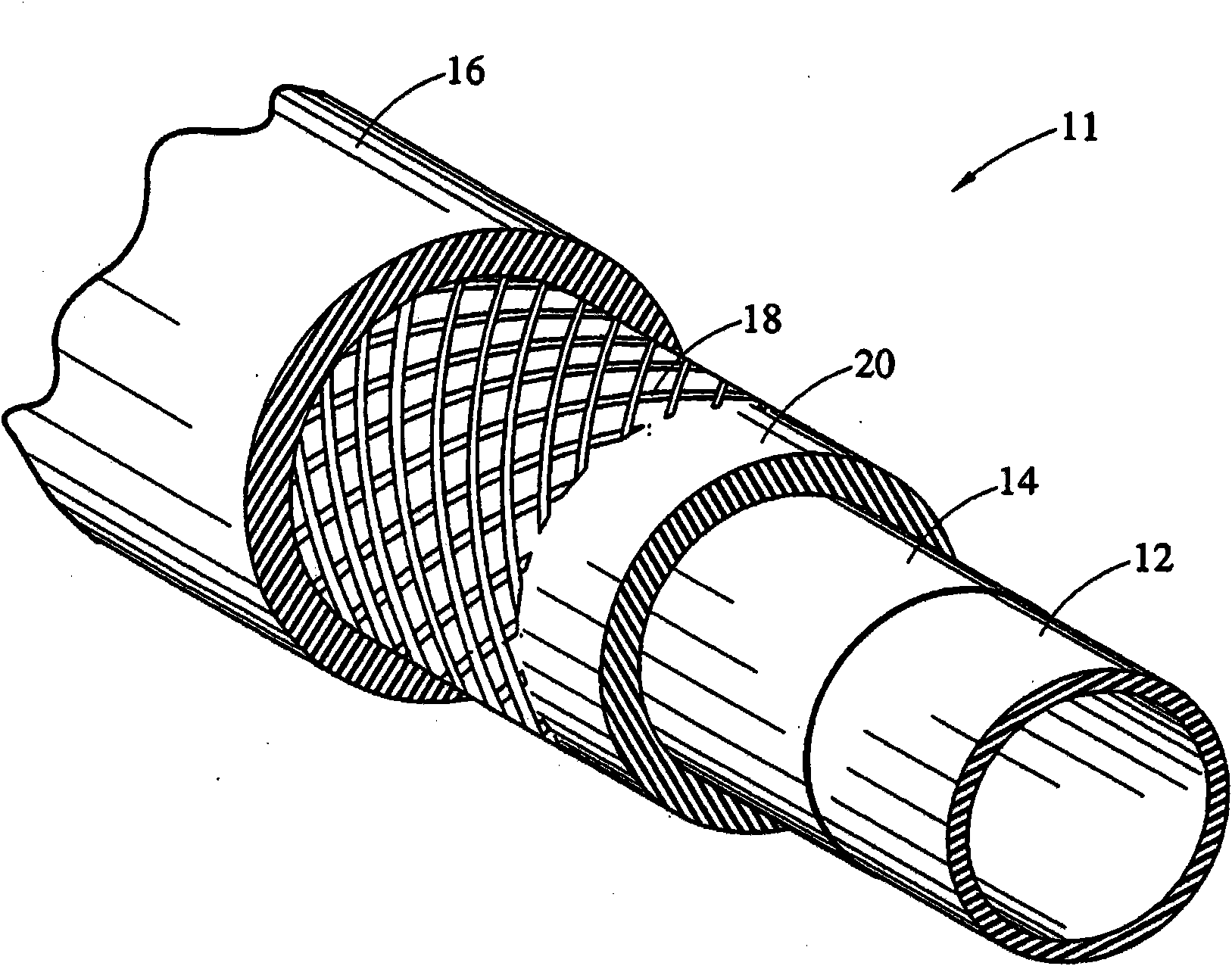
[0016] refer to figure 1 , shows a hose constructed in accordance with one embodiment of the invention. The hose 11 includes an inner tube 12 , an intermediate thermoplastic barrier layer 14 of ethylene vinyl alcohol copolymer (EVOH), and an outer cover layer 16 . Optionally, the hose 11 may include a reinforcement layer 18 disposed somewhere within the hose. As another option, hose 11 may include one or more tie layers and / or adhesive coatings between the various layers. figure 1 The reinforcement layer 18 applied on the tie layer 20 is shown. The intermediate layer 14 may be arranged within one of the rubber layers, thus effectively dividing said rubber layer into two separate layers.

[0017] The intermediate barrier layer 14 comprises EVOH preferably having an ethylene content of less than 30 mole percent. The thickness of the intermediate layer may range from 0.025 to 0.76 mm (1 to 30 mils), preferably from 0.025 to 0.38 mm (1 to 15 mils), or from 0.05 to 0.25 mm (2 t...


PUM

PropertyMeasurementUnit
thicknessaaaaaaaaaa
thicknessaaaaaaaaaa
thicknessaaaaaaaaaa

Abstract

A flexible hose having a non-fluorinated rubber inner tube, a non-fluorinated rubber outer cover, an intermediate barrier layer consisting essentially of ethylene- vinyl alcohol copolymer (EVOH) having an ethylene content less than 30 mole %, and preferably a textile reinforcement between said barrier layer and said outer cover. A non-fluorinated rubber tie layer may be included between the barrier and the reinforcement. Permeability to ethanol- and methanol-containing fuels is very low.

Description

technical field [0001] The present invention relates generally to flexible fuel hoses having low permeability to modern ethanol-containing fuels, and more particularly to hoses having an intermediate barrier layer of ethylene-vinyl alcohol copolymer between inner and outer layers of non-fluorinated rubber . Background technique [0002] The increasing use of alcohol (including ethanol)-containing motor vehicle fuels, coupled with stringent emission standards for fuel system components, has necessitated improvements in conventional flexible hose construction. Conventional fuel hose construction uses economical oil-resistant rubber materials such as nitrile rubber (NBR), nitrile-polyvinyl chloride blends (NBR-PVC), epichlorohydrin (ECO), and the like. Improved hoses for alcohol-containing fuels now commonly use various fluorine-containing polymers such as commonly referred to as FKM, PVDF, ETFE, FEP, EFEP, PCTFE, THV, PTFE, and the like (hereinafter collectively referred to a...

Claims


Application Information

Patent Timeline
Patent Type & Authority Applications(China)
IPC IPC(8): F16L11/20F16L11/112C08J5/00C08F10/02B29C48/09B29C48/151B29C48/18
CPCB29C47/021B29K2277/00B29K2995/0069B32B1/08B32B25/08B29K2105/0827B29K2105/0809B29K2105/0836B29L2023/005B29D23/001B29C47/06B32B27/30B29K2201/00B29K2023/086F16L11/085B29K2277/10B29K2267/00B29C47/0023F16L2011/047C08F210/02B29K2077/00B32B5/022B32B5/024B32B5/026B32B7/12B32B25/10B32B27/12B32B27/306B32B27/32B32B2262/0223B32B2262/0261B32B2262/0269B32B2262/0276B32B2262/04B32B2262/103B32B2307/546B32B2307/7242B32B2307/7265B32B2597/00B32B2605/00B29C48/09B29C48/151B29C48/18Y10T428/1383C08F216/06
Inventor L·D·米勒D·S·斯特里普H·塔克
Owner THE GATES CORP
Why Eureka
Eureka Blog
Learn More