Magnetoresistance sensor and method of operating a magnetoresistance sensor

A magnetoresistive sensor, sensor technology, applied in the field of operating magnetoresistive sensors, program elements, and computer readable media, can solve the problem that AMR speed sensors cannot provide air gap capability, sensor head output signal reduction, signal processing and adjustment units are heavy requirements, etc.

Inactive Publication Date: 2010-10-06
NXP BV
View PDF0 Cites 14 Cited by
  • Summary
  • Abstract
  • Description
  • Claims
  • Application Information

AI Technical Summary

Problems solved by technology

[0008] The main disadvantage of Barber electrode sensors is the reduced sensitivity caused by this auxiliary field
And, for an increased air gap, the output signal of the sensor head decreases, which leads to heavy demands on the signal processing and conditioning unit of the smart sensor system
Thus, prior art AMR speed sensors equipped with standard magnets composed of iron, ferrite, or AlNiCo alloys do not provide the air gap capability required in many applications such as automotive drivetrains

Method used


Image

  • Magnetoresistance sensor and method of operating a magnetoresistance sensor
  • Magnetoresistance sensor and method of operating a magnetoresistance sensor
  • Magnetoresistance sensor and method of operating a magnetoresistance sensor

Examples


Embodiment Construction

[0034] The illustrations in the figures are schematic. In different drawings, similar or identical elements are indicated by similar or identical reference symbols.

[0035] In the following, reference will be made to Figure 1 to Figure 5 Some basic principles of a magnetoresistive sensor system according to example embodiments are described.

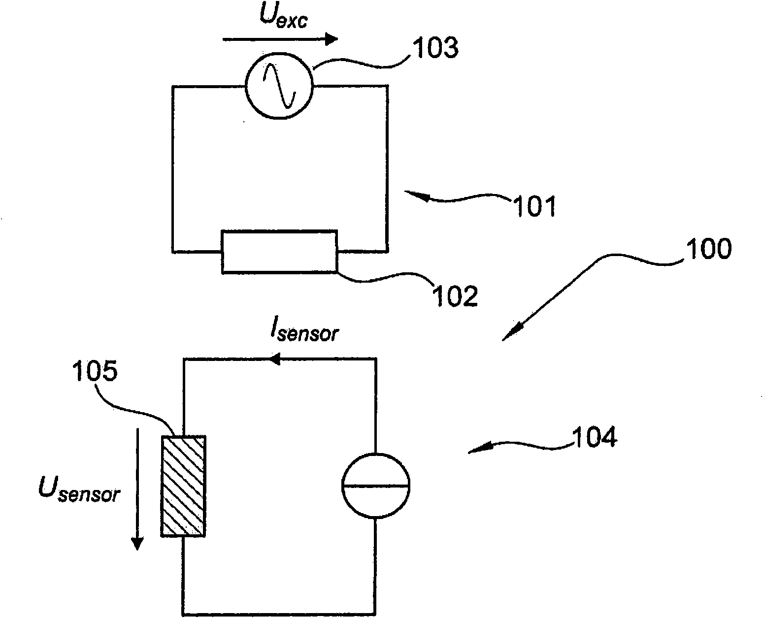
[0036] figure 1 A simplified circuit diagram representing a current fed anisotropic magnetoresistive sensor (AMR sensor) 100 with sinusoidal excitation. figure 1 A magnetic field source 101 comprising a drive coil 102 and an oscillating voltage source 103 (eg an oscillator) is shown in detail. also, figure 1 A magnetoresistive sensor 104 comprising an AMR element 105 is shown. Specifically, it should be noted that the easy axis of the AMR element 105 has figure 1 in a roughly vertical direction, that is, along the figure 1 The voltage shown in U sensor direction, while the direction of the magnetic field induced by the driving ...


PUM


Abstract

Amagnetoresistive sensor system (400) is provided, wherein the system comprises a magnetic field source (402), a magnetoresistive sensor (403) having an easy axis, and a differentiation element (404), wherein the magnetic field source (402) is adapted to emit an auxiliary magnetic field generated from an oscillating input signal (401), wherein the auxiliary magnetic field is orthogonal to the easy axis of the magnetoresistive sensor (403), wherein the magnetoresistive sensor (403.) is adapted to sense a signal associated to a superposition of an external magnetic field and the auxiliary alternating magnetic field, and wherein the differentiation element (404) is adapted to differentiate the sensed signal.

Description

technical field [0001] The present invention relates to magnetoresistive sensors. [0002] The invention also relates to a method of operating a magnetoresistive sensor. [0003] Also, the present invention relates to program elements. [0004] Furthermore, the present invention relates to computer readable media. Background technique [0005] Magneto-resistive sensors such as anisotropic magnetoresistive sensors (AMR) or giant magnetoresistive sensors (GMR) are widely used today. For example, AMR sensors are critical components in many automotive applications, such as anti-lock braking systems (ABS), engine management, transmission or safety systems. Especially in the field of automotive transmission, air gap capability is required. [0006] Typically, a magnetoresistive sensor for rotational speed measurement is linearized by a Barber pole structure. Because Barber electrode sensors have two stable output characteristics, a bias magnet must be employed to prevent flip...

Claims


Application Information

Patent Timeline
Patent Type & Authority Applications(China)
IPC IPC(8): G01R33/09
CPCG01R33/093B82Y25/00G01R33/096
Inventor 斯蒂芬·布茨曼马库斯·普洛查斯卡
Owner NXP BV
Why Eureka
Try Eureka