

Control method of plasma by magnetic field in an exhaust gas treating apparatus and an exhaust gas treating apparatus using the same
An exhaust gas treatment device and plasma technology, applied in plasma, gas treatment, separation methods, etc., can solve problems such as damage to reaction tubes, increased consumption, and problems with device durability, and achieve the generation of magnetic fields, The effect of improving processing efficiency and preventing scattering
Active Publication Date: 2010-10-13
CLEAN TECH CO LTD
View PDF6 Cites 16 Cited by
- Summary
- Abstract
- Description
- Claims
- Application Information
AI Technical Summary
Problems solved by technology
[0004] However, the method of increasing the plasma length (discharge distance) in (1) improves the processing capacity itself, and although the processing efficiency is improved, there is a problem that the energy consumption increases.
[0005] In addition, the method of reducing the diameter of the reaction tube in (2) improves the treatment efficiency by increasing the contact efficiency between the plasma and the exhaust gas, but on the contrary, the absolute amount of treatment decreases, and in addition, because the tube wall of the reaction tube is close to the plasma The reaction tube is easily damaged, and there is a problem with the durability of the device
[0006] In addition, the method (3) of introducing exhaust gas into the reaction tube from the tangential direction improves the processing efficiency because the contact efficiency between the plasma and the exhaust gas improves, but there is a problem that the structure of the introduction part of the exhaust gas in the reaction tube becomes complicated.
Method used
View moreImage
Smart ImageViewing Examples

Examples
Embodiment
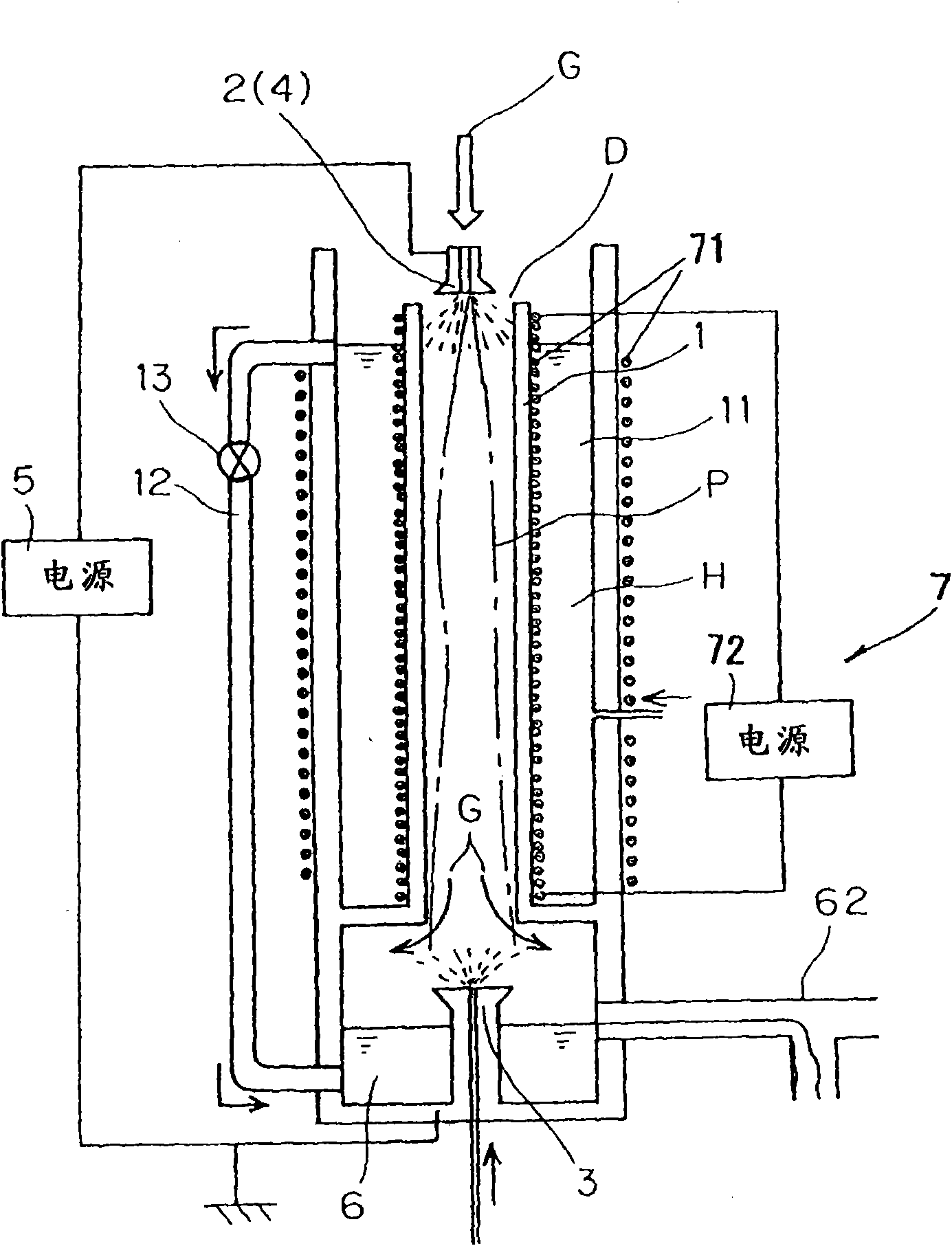
[0065] Such as figure 1 As shown, a coil 71 is arranged as a magnetic field generating unit 7 on the outer peripheral portion of the reaction tube 1 and the water-cooled jacket 11 constituting the plasma discharge part for introducing the exhaust gas G, and a current (DC current), so that a magnetic field (a magnetic field in which the lines of force flow from the upper electrode 2 toward the lower electrode 3) is generated, and CF is decomposed as exhaust gas G 4 .
[0066] Table 1 shows the results.
[0067] Table 1
[0068] Current value (A)
[0069] As shown in Table 1, it was confirmed that the larger the current value flowing through the coil 71, the CF 4 The higher the decomposition rate is.
Login to View More PUM
 Abstract
To present a control method of plasma by magnetic field in an exhaust gas treating apparatus and an exhaust gas treating apparatus using the same, in a simple method and structure, without extremely increasing the consumption of energy, or without lowering the absolute amount of treatment. [Solving Means] In an exhaust gas treating apparatus for decomposing and treating an exhaust gas introduced into a reaction tube 1 by the plasma generated in the reaction tube 1, by generating a magnetic field in the reaction tube 1, the state of the plasma generated in the reaction tube 1 is controlled.
Description
technical field [0001] The present invention relates to a method for controlling plasma using a magnetic field in an exhaust gas treatment device and an exhaust gas treatment device using the same, in particular to controlling the state of the plasma by generating a magnetic field so that the exhaust gas performed by the plasma can be improved. A method of controlling plasma using a magnetic field in an exhaust treatment device with high treatment efficiency and an exhaust treatment device using the same. Background technique [0002] Conventionally, an exhaust gas treatment device using plasma has been proposed and put into practical use in the process of treating exhaust gas generated in the manufacture of semiconductors, etc. (for example, refer to Patent Document 1). [0003] In this exhaust gas treatment device, as a method of improving the decomposition efficiency of the treated exhaust gas, there are the following methods, etc.: (1) a method of increasing the plasma l...
Claims
Login to View More Application Information
Patent Timeline
 IPC IPC(8): B01D53/32B01D53/68B01D53/70
CPCB01D2257/2066B01D53/32B01D2258/0216B01D2259/818B01D2257/204H05H1/24H05H1/50H05H2245/17B01D53/323B01D53/70B01D2259/814B01J19/08B01J19/087B01J19/088
Inventor淡路敏夫中山贵志田中敏夫
OwnerCLEAN TECH CO LTD