Single-electrical signal-stimulated rotation ultrasonic motor
What is Al technical title?
Al technical title is built by PatSnap Al team. It summarizes the technical point description of the patent document.
An ultrasonic motor, single electrical signal technology, applied in the direction of generator/motor, piezoelectric effect/electrostrictive or magnetostrictive motor, electrical components, etc. problems, to achieve the effect of reducing installation requirements, reducing control difficulty, and reducing manufacturing costs
Inactive Publication Date: 2010-10-13
SUZHOU UNIV OF SCI & TECH +1
View PDF4 Cites 23 Cited by
Summary
Abstract
Description
Claims
Application Information
AI Technical Summary
This helps you quickly interpret patents by identifying the three key elements:
Problems solved by technology
Method used
Benefits of technology
Problems solved by technology
[0005] However, several types of ultrasonic motors based on mode conversion reported in the existing literature have problems such as complex structure, difficult manufacturing, high requirements for manufacturing and assembly, and high cost, which restrict their application in industrial production.
Method used
Image
Click on the blue label to locate the original text in one second.
Reading with bidirectional positioning of images and text.
Examples
Embodiment Construction
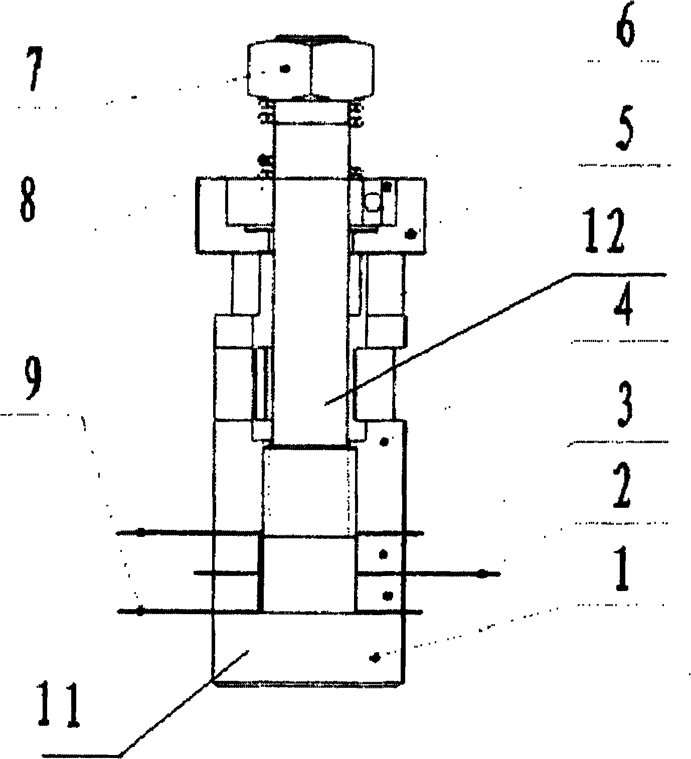
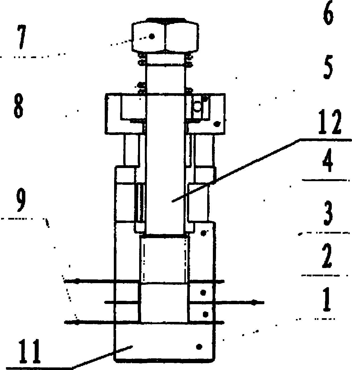
[0023] Such as figure 1 As shown, the ultrasonic motor excited by a single electric signal of the present invention includes a mandrel 1 and a group of piezoelectric ceramic sheets 3, a window-shaped dislocation mode converter 4, a friction disc 5, a bearing 6, The spring 8 and the nut 7, the piezoelectric ceramic sheet 3 are connected with the electrode sheets 2 and 9, the mandrel 1, the piezoelectric ceramic sheet 3, the electrode sheets 2 and 9, and the window-shaped dislocation mode converter 4 constitute the stator part of the ultrasonic motor , The friction disc 5 and the bearing 6 constitute the rotor part of the ultrasonic motor, and the spring 8 and the nut 7 constitute the positive pressure preload adjustment mechanism of the rotor and the stator part of the ultrasonic motor.
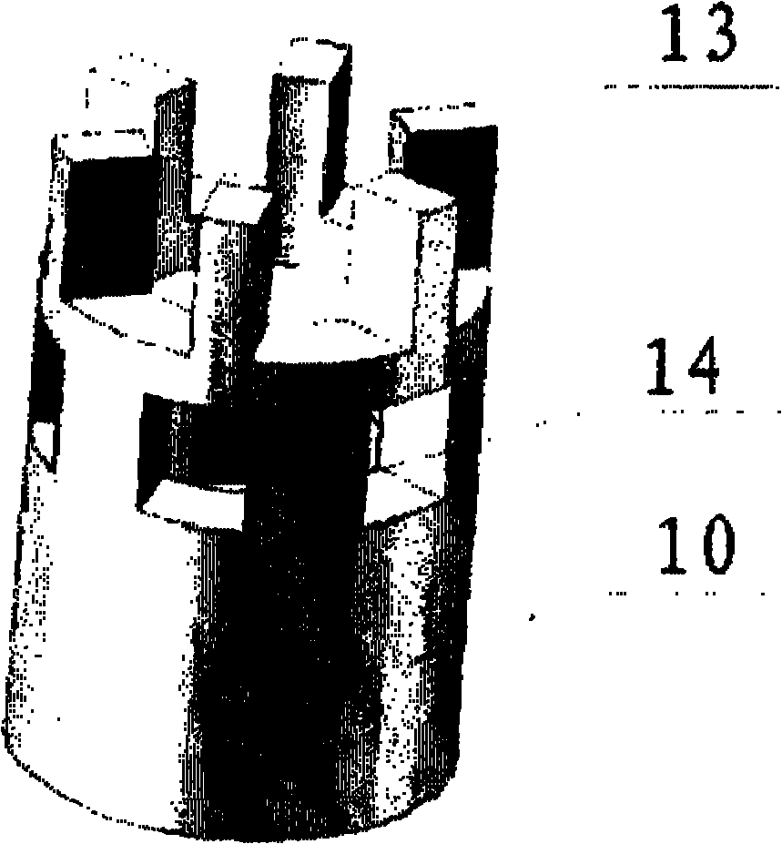
[0024] Wherein, the window-shaped dislocation mode converter 4 is composed of two parts: a lower cylinder part 10 and an upper window-shaped dislocation part, wherein the window-shaped disloca...
PUM
Abstract
The invention discloses a single-electrical signal-stimulated rotation ultrasonic motor which comprises a mandrel, a group of piezoelectric ceramic sheets, a window-shaped staggered mode converter, a friction disk, a bearing, a spring and a nut, wherein the piezoelectric ceramic sheets, the window-shaped staggered mode converter, the friction disk, the bearing, the spring and the nut are sequentially sleeved on the mandrel, the piezoelectric ceramic sheets are connected with electrode sheets, the mandrel, the piezoelectric ceramic sheets, the electrode sheets and the window-shaped staggered mode converter form the stator part of the ultrasonic motor, the friction disk and the bearing form the rotor part of the ultrasonic motor, and the spring and the nut form a positive-pressure pretightening force adjusting mechanism of the rotor and the stator parts of the ultrasonic motor. In the invention, a single-electrical signal-stimulated working mode is adopted, the elliptical orbit motion of stator end surface particles is realized by utilizing the longitudinal vibration mode of the group of piezoelectric ceramic sheets, a rotor is driven to rotate, and the ultrasonic motor has simple control-driven system, easy manufacture, easy miniaturization and integration, low cost, small control difficulty and broad application prospect.
Description
technical field [0001] The invention belongs to the field of ultrasonic motors, in particular to a piezoelectric ultrasonic motor excited by a single electric signal. Background technique [0002] Ultrasonic Motor (USM), also known as ultrasonic motor, is an electromechanical coupling device that realizes electrical energy-mechanical energy conversion through the inverse piezoelectric effect of piezoelectric materials. Due to the advantages of electromagnetic interference and strong environmental adaptability, it has been increasingly widely used in medical, aerospace, robotics, MEMS and other technical fields. [0003] According to the vibration theory, ultrasonic motors can be divided into traveling wave ultrasonic motors and standing wave ultrasonic motors. Most traveling wave and standing wave ultrasonic motors use two sets of piezoelectric ceramic vibrators to excite the stator to generate two vibration modes with a certain phase difference. In this state, the particle...
Claims
Application Information
Patent Timeline
Application Date:The date an application was filed.
Publication Date:The date a patent or application was officially published.
First Publication Date:The earliest publication date of a patent with the same application number.
Issue Date:Publication date of the patent grant document.
PCT Entry Date:The Entry date of PCT National Phase.
Estimated Expiry Date:The statutory expiry date of a patent right according to the Patent Law, and it is the longest term of protection that the patent right can achieve without the termination of the patent right due to other reasons(Term extension factor has been taken into account ).
Invalid Date:Actual expiry date is based on effective date or publication date of legal transaction data of invalid patent.