Eureka AIR delivers breakthrough ideas for toughest innovation challenges, trusted by R&D personnel around the world.

Method and apparatus of particulate removal from gasifier components

A technology of particulate matter and components, applied in the field of gasification systems and processes, can solve problems such as blockage of downstream components and dangers of syngas coolers

Active Publication Date: 2010-10-20
AIR PROD & CHEM INC
View PDF3 Cites 4 Cited by
  • Summary
  • Abstract
  • Description
  • Claims
  • Application Information

AI Technical Summary

Problems solved by technology

This spontaneous release of large deposits often leads to clogging of downstream components of the syngas cooler
Finally, falling sediments pose a hazard to workers performing maintenance and / or repairs in syngas coolers

Method used


Image

  • Method and apparatus of particulate removal from gasifier components
  • Method and apparatus of particulate removal from gasifier components
  • Method and apparatus of particulate removal from gasifier components

Examples


Embodiment Construction

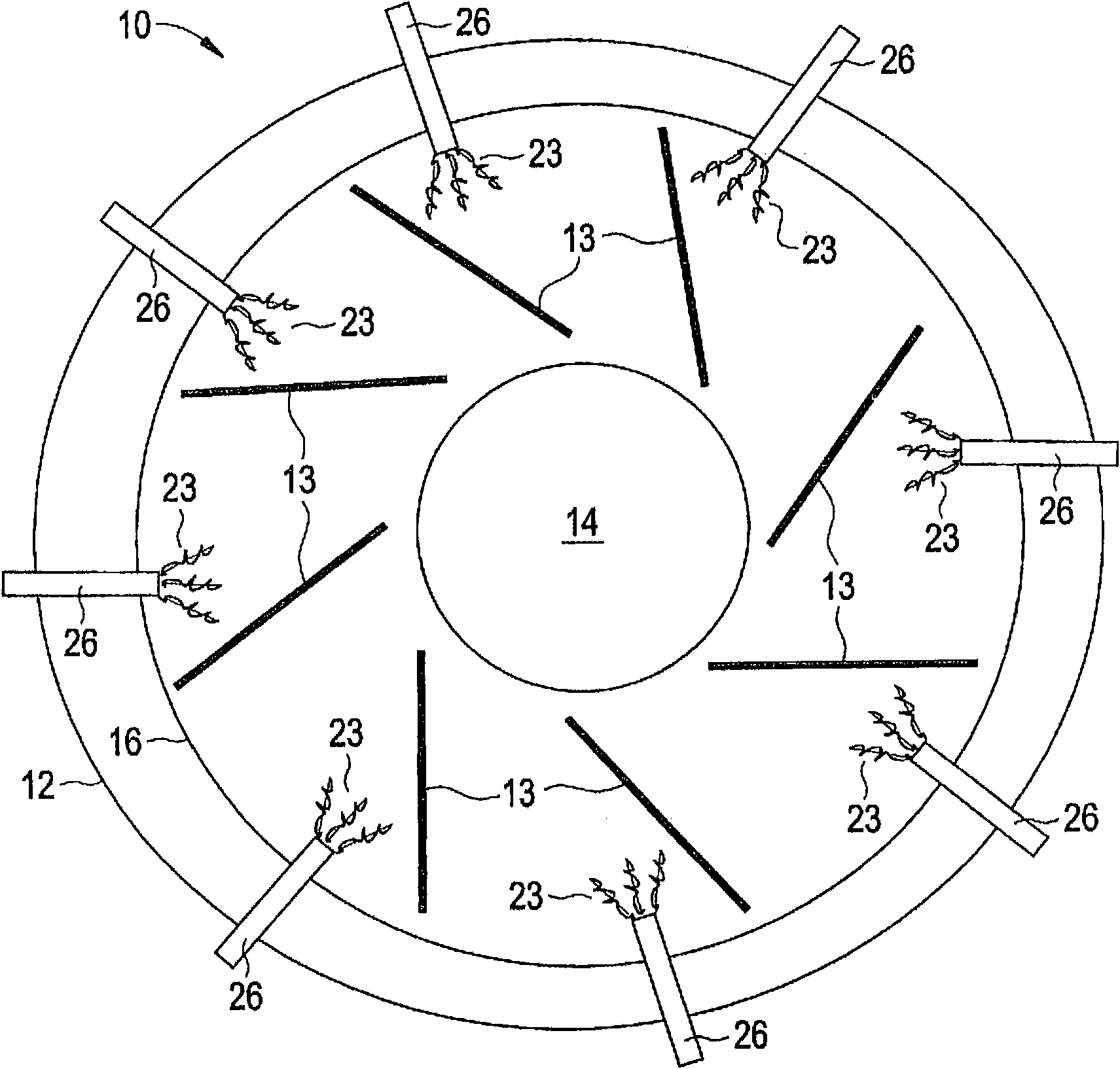
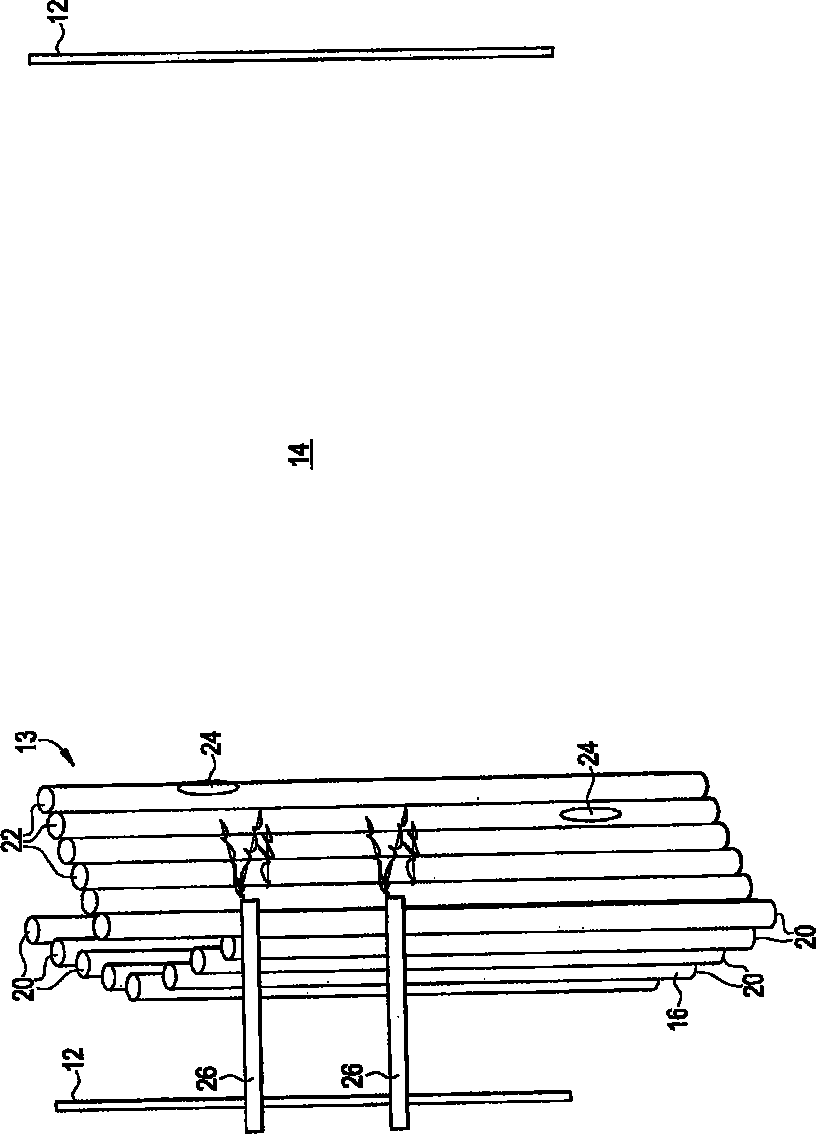
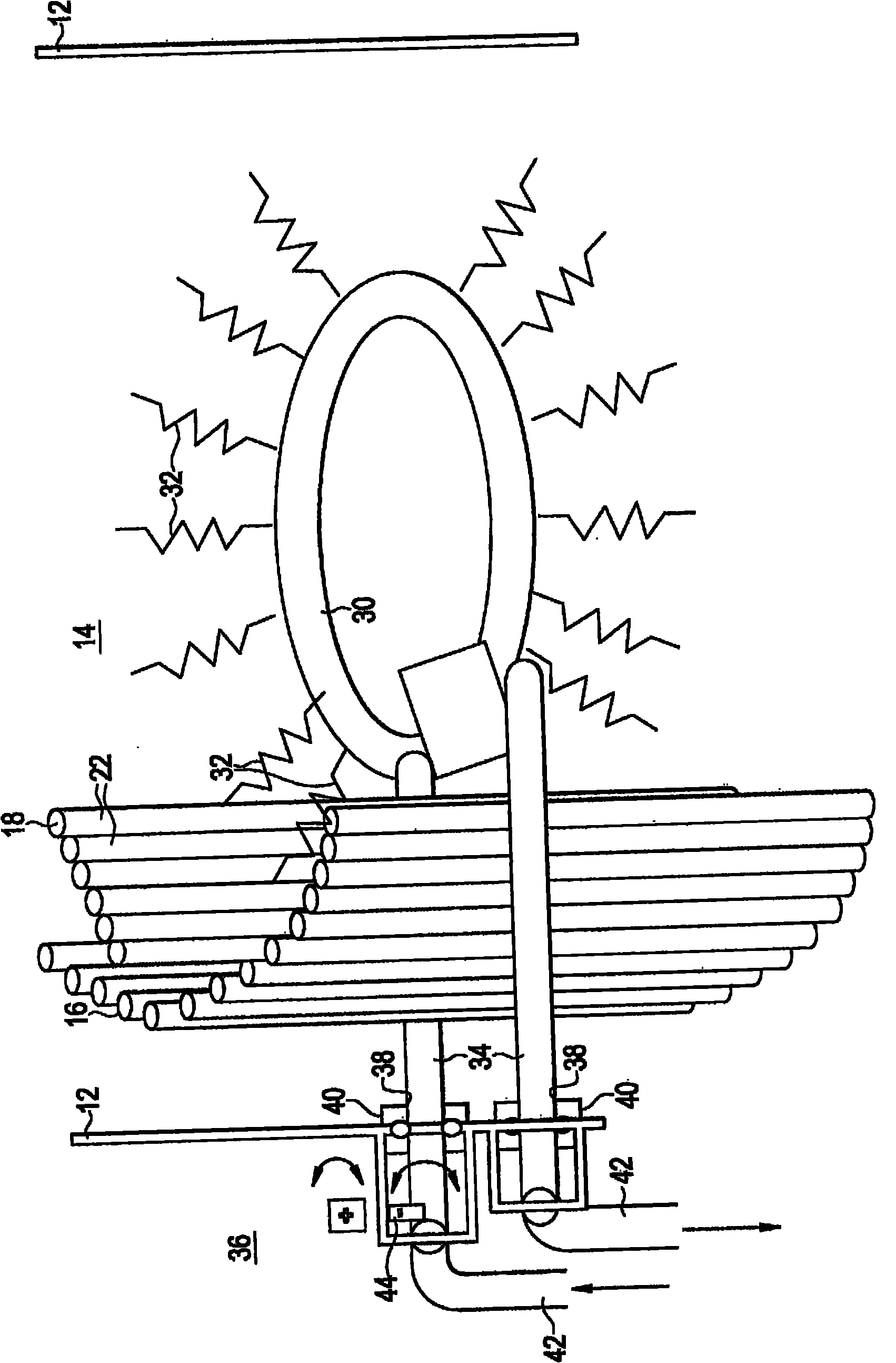
[0025] figure 1 Shown is one embodiment of a gasification system component, in this example a syngas cooler 10 . The syngas cooler 10 includes a vessel shell 12 that defines an outer surface of the syngas cooler 10 . A number of internal components may be disposed inside the vessel shell 12 within the interior 14 of the syngas cooler 10 . Some of these components, including the tube cage 16 and one or more sets of screens 18 , are constructed and arranged to facilitate the transfer of thermal energy from the syngas in the syngas cooler 10 to the tube cage 16 and / or the screens 18 . Although figure 1 Eight sets of screens 18 are shown in , but it should be understood that other numbers of sets of screens 18 may be provided in the interior 14 of the syngas cooler 10 , such as 10 or 12 sets of screens 18 . Such as figure 2 As shown in , the tube cage 16 includes a plurality of individual cage tubes 20 and each set of screens 18 includes a plurality of screen tubes 22 . Duri...


PUM


Abstract

The invention relates to a method and an apparatus of particulate removal from gasifier components. Disclosed is a method of removing a particulate layer from a gasification system component including locating a shedding apparatus in operable communication with the gasification system component. A force is transmitted from the shedding apparatus into the gasification system component and the particulate layer is shed from the gasification system component as a result of the force. Further disclosed is a syngas cooler for a gasification system including a vessel and a plurality of thermal energy transfer platens located in the vessel. A shedding apparatus is in operable communication with the plurality of platens and is capable of shedding a particulate layer from the plurality of platens by transmitting a force to the plurality of platens.

Description

technical field [0001] The subject matter disclosed herein relates to gasification systems and processes. More specifically, the subject matter relates to the removal of particulate matter layers from gasification system components. Background technique [0002] Gasification is a process used to generate power, chemicals and industrial gases from carbonaceous or hydrocarbon feedstocks such as coal, heavy oil and petroleum coke. Gasification converts carbonaceous or hydrocarbon feedstocks into synthesis gas, also known as "syngas", consisting primarily of hydrogen and carbon monoxide. The resulting syngas is a feedstock for the manufacture of useful organic compounds or can be used as a clean fuel to generate power. [0003] In a typical gasification plant, a carbonaceous or hydrocarbon feedstock is contacted with molecular oxygen in a partial oxidation reactor (gasifier) ​​at high pressure. The feedstock reacts with oxygen molecules and forms synthesis gas. Non-gasifiabl...

Claims


Application Information

Patent Timeline
Patent Type & Authority Applications(China)
IPC IPC(8): C10J3/72C10K1/04C01B3/36
CPCF28D7/0041F28G15/02Y02E20/18C10J3/72C10J3/86F28G9/00F28D7/00C01B3/36F22B1/1846B01D47/06F28G7/00C10J3/526C10J3/74C10J2200/36
Inventor S·C·拉塞尔J·M·斯托里R·H·戈捷
Owner AIR PROD & CHEM INC
Why Eureka
Eureka Blog
Learn More