Electro-hydraulic control system for concrete or coal slime conveying device and method for controlling system

A technology of electro-hydraulic control system and delivery device, which is applied in the direction of fluid pressure actuation device, fluid pressure actuation system components, mechanical equipment, etc. Leakage and other problems, to achieve the effect of low manufacturing and maintenance costs, long service life and high reliability

Inactive Publication Date: 2010-10-20
秦月明
View PDF4 Cites 20 Cited by
  • Summary
  • Abstract
  • Description
  • Claims
  • Application Information

AI Technical Summary

Problems solved by technology

The Chinese invention patent with the patent number of 200510031258.9 discloses an auxiliary energy storage and flow increasing device (2) for the hydraulic system of a concrete pump. One is composed of pumping oil circuit, distribution oil circuit and stirring oil circuit, which is the so-called three-pump oil supply; the former adopts the working method of single oil inlet and double oil return, When the hydraulic system is working, it needs to rely on the mutual closure of the electro-hydraulic directional valve to maintain the pressure, and the long-term closure and pressurization will increase the internal leakage of the electro-hydraulic directional valve, and also cause the oil temperature to rise, shortening the hydraulic pump and the electro-hydraulic directional valve. valve life, high energy consumption
The latter needs to control the cost, because the power of the power plant is fixed, in order to ensure that the displacement of the hydraulic pump used in the pumping oil circuit is large enough, the displacement of the hydraulic pump used in the swing distribution oil circuit should not be too large, in order to ensure the rapid reversing of the swing , the swing oil circuit needs to add constant pressure and energy storage and other auxiliary devices. Long-term constant pressure will lead to increased oil temperature, reduced work efficiency, high energy consumption, and easy damage to the hydraulic pump. If a high-power power device is used, the economy will decline.
When the two work, all cylinders need to be in a state of pressure, the working noise is large, and the failure rate is high

Method used


Image

  • Electro-hydraulic control system for concrete or coal slime conveying device and method for controlling system
  • Electro-hydraulic control system for concrete or coal slime conveying device and method for controlling system
  • Electro-hydraulic control system for concrete or coal slime conveying device and method for controlling system

Examples


Embodiment Construction

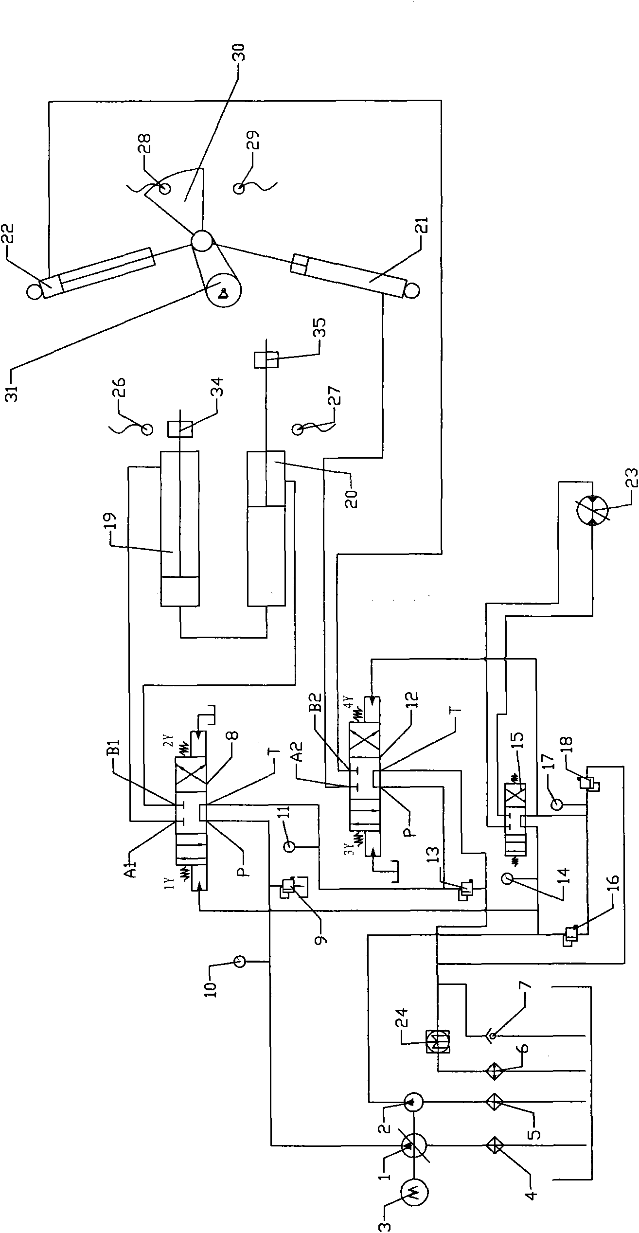
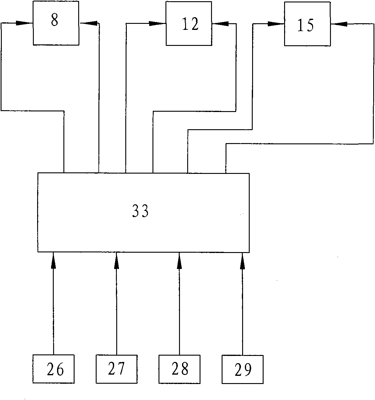
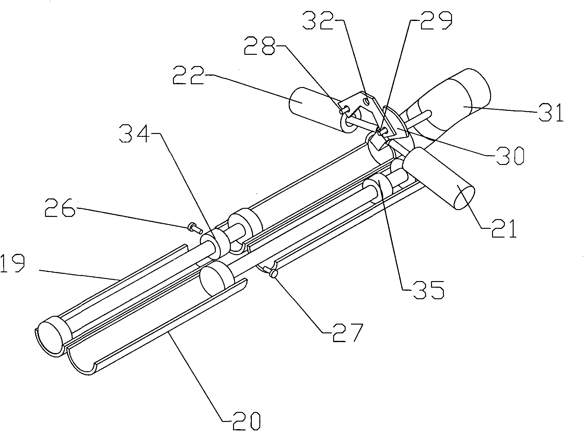
[0020] Such as Figure 1~2 As shown, an electro-hydraulic control system applied to a concrete or coal slime conveying device and a method for controlling the system include a main hydraulic pump 1, an auxiliary hydraulic pump 2, and a power device that drives the main hydraulic pump 1 and the auxiliary hydraulic pump 2 to work 3. The unloading overflow valve 9 for setting the pumping pressure, the unloading overflow valve 13 for setting the swing pressure, the first pumping cylinder 19 and the second pumping cylinder 20 for pushing concrete, It is used to connect to the swing S pipe 31 of the discharge port of the aforementioned two pumping cylinders, and is used to drive the swing cylinders 21 and 22 of the swing S pipe 31 to swing; the swing S pipe 31 is provided with a fan-shaped block 30 that can swing with it , the delivery device is provided with the first and second sensors 28 and 29 for detecting the position of the swing S pipe 31, the third and fourth sensors 26 and...


PUM


Abstract

The invention discloses an electro-hydraulic control system for a concrete or coal slime conveying device and a method for controlling the system. The electro-hydraulic control system comprises a programmable logic controller PLC, a swinging S tube, a sensor, a pumping oil cylinder, a hydraulic pump, an overflow valve, three M-shaped three-position four-way electro-hydraulic directional control valves, an oil tank, an oil stirring path, a pumping oil path and a swinging oil path, wherein a T port of a first M-shaped three-position four-way electro-hydraulic directional control valve is connected with a P port of a second M-shaped three-position four-way electro-hydraulic directional control valve; the baffles of the pumping oil cylinder and the swinging oil cylinder act on the sensor, so that a signal is emitted from the sensor and received by the PLC; the PLC sequentially acts on the two electro-hydraulic directional control valves according to a program set therein; and the two electro-hydraulic directional control valves control the on-off of oil paths flowing to the pumping oil cylinder and the swinging oil cylinder. The electro-hydraulic control system has the advantages of low oil temperature, low noise, long service life, low manufacturing and maintenance cost, low energy consumption and high reliability.

Description

【Technical field】 [0001] The invention relates to the field of hydraulic systems, in particular to an electro-hydraulic control system applied to a concrete or coal slime conveying device and a method for controlling the system. 【Background technique】 [0002] The electro-hydraulic control system of the concrete or coal slime conveying device is applied in the concrete or coal slime conveying to complete the functions of pumping, distributing and mixing of concrete or coal slime. The Chinese invention patent with the patent number of 200510031258.9 discloses an auxiliary energy storage and flow increasing device (2) for the hydraulic system of a concrete pump. One is composed of pumping oil circuit, distribution oil circuit and stirring oil circuit, which is the so-called three-pump oil supply; the former adopts the working method of single oil inlet and double oil return, When the hydraulic system is working, it needs to rely on the mutual closure of the electro-hydraulic ...

Claims


Application Information

Patent Timeline
Patent Type & Authority Applications(China)
IPC IPC(8): F15B21/08F15B15/02
Inventor 秦月明
Owner 秦月明
Why Eureka
Try Eureka