Vibrating table short circuit ring cooling structure and preparation method thereof

A cooling structure and short-circuit ring technology, which is applied in vibration testing, machine/structural component testing, measuring devices, etc., can solve equipment safety hazards, water leakage and other problems, and achieve low cost, simple processing technology, and high-efficiency cooling.

Active Publication Date: 2010-10-20
SUZHOU DONGLING VIBRATION TEST INSTR
View PDF7 Cites 4 Cited by
  • Summary
  • Abstract
  • Description
  • Claims
  • Application Information

AI Technical Summary

Problems solved by technology

However, in this short-circuit ring cooling mechanism, if the water pipe joints are not handled properly, water leakage will often occur, which will bring great safety hazards to the equipment.

Method used


Image

  • Vibrating table short circuit ring cooling structure and preparation method thereof
  • Vibrating table short circuit ring cooling structure and preparation method thereof
  • Vibrating table short circuit ring cooling structure and preparation method thereof

Examples


Embodiment 1

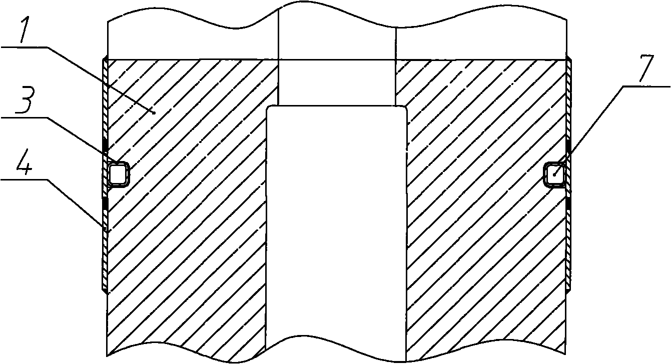
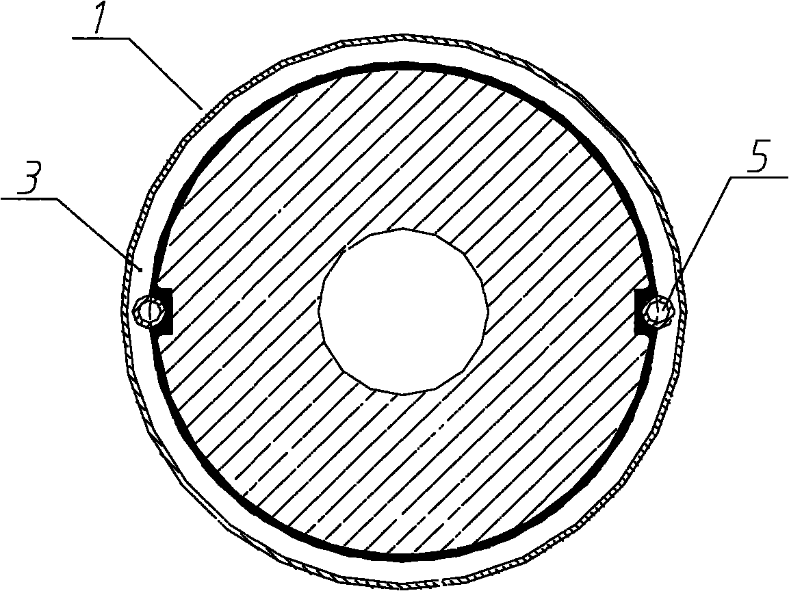
[0031] Example 1 as Figure 2~3 As shown, the short-circuit ring cooling structure of the vibrating table includes a short-circuit ring 4 arranged on the central magnetic pole 1. Two deep holes 8 are arranged in the central magnetic pole along the axial direction, and a cooling water pipe 5 with a closed upper end is respectively arranged in the deep holes. , and one of the cooling water pipes communicates with the peripheral cooling water supply equipment to form a water inlet channel, while the other cooling water pipe forms a return water channel, and an annular groove 3 is opened on the outer wall of the central magnetic pole 1, and the two cooling water pipes pass through it. An opening provided on the upper pipe wall communicates with the annular groove 3, and the annular groove wall is fixedly connected with the corresponding cooling water pipe wall by all-copper surfacing welding. The width of the short-circuit ring is greater than that of the annular groove, and the in...

Embodiment 2

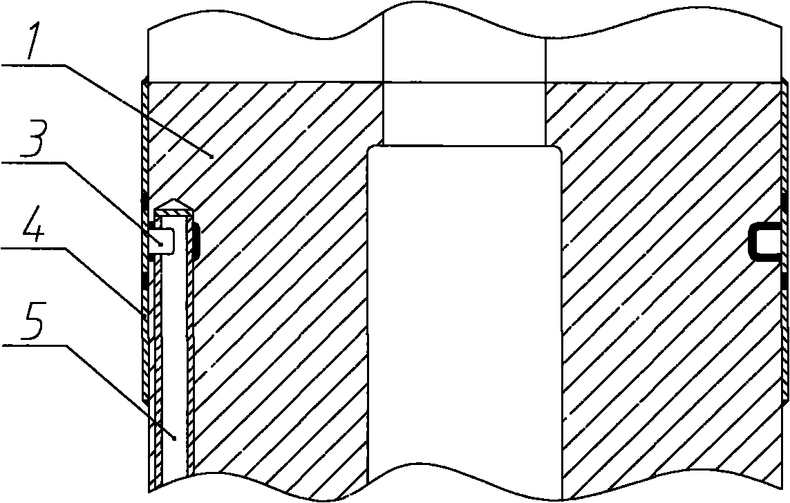
[0038] Example 2 as Figure 5-6 As shown, the short-circuit ring cooling structure of the vibrating table includes a short-circuit ring 4 arranged on the inner wall of the magnetic cylinder 2, two deep holes are arranged in the inner wall of the magnetic cylinder along the axial direction, and an annular groove 3' is opened on the inner wall of the magnetic cylinder. A cooling water pipe 5 with a closed upper end is respectively arranged in the deep holes, and the two cooling water pipes communicate with the annular groove 3' through an opening provided on the upper pipe wall, and the annular groove wall is fully copper stacked with the corresponding cooling water pipe wall. One of the cooling water pipes is also connected with the external cooling water supply equipment. The width of the short-circuit ring 4 is greater than the width of the annular groove, and the parts on the inner wall corresponding to the edges of both sides of the annular groove are sealed with the inner w...


PUM


Abstract

The invention relates to a vibrating table short circuit ring cooling structure and a preparation method thereof. The short circuit ring cooling structure comprises a short circuit ring arranged on a magnetic cylinder and / or central magnetic pole, wherein the inner wall of the magnetic cylinder or the outer wall of the central magnetic pole is provided with at least one annular groove; the annular groove is communicated with at least two deep holes which are axially formed in the magnetic cylinder or the central magnetic pole; at least one deep hole is also communicated with a cooling water supply device to form a water inlet passage; the rest deep holes are communicated with the exterior of the magnetic cylinder or the central magnetic pole to form a water discharge passage; and the short circuit ring covers the annular groove and is hermetically and circularly connected with the inner wall of the magnetic cylinder or the outer wall of the central magnetic pole. The vibrating table short circuit ring cooling structure can efficiently cool the short circuit ring and has the advantages of high sealing property, no threat of leakage of the cooling liquid, simple machining process and low cost.

Description

technical field [0001] The invention relates to an electrodynamic vibration test equipment and a construction method thereof in the field of vibration test technology, in particular to a short-circuit ring cooling structure of a vibration table and a preparation method thereof. Background technique [0002] In commonly used electric vibrating tables, short-circuit copper rings are generally arranged on the center magnetic pole and the magnetic cylinder. Its function is to change the equivalent impedance of the magnetic circuit system, increase the input current and increase the output electromotive force, and can also be used as a compensation coil to offset or weaken the dynamic vibration. The constant and angular frequency components of the electromotive force generated by the circular motion increase the amplitude and reduce the distortion. But at the same time, there will be a large eddy current in the short-circuit copper ring, and a large amount of heat will be generat...

Claims


Application Information

Patent Timeline
IPC IPC(8): G01M7/02
Inventor 陈俊赵征
Owner SUZHOU DONGLING VIBRATION TEST INSTR
Why Eureka
Try Eureka