Rescue robot

A rescue robot and steering gear technology, applied in the field of robot rescue, can solve the problems of complex mechanical transmission, high production cost, and high quality, and achieve the effect of small size, light weight, and simple structure

Inactive Publication Date: 2010-10-27
SHANGHAI MARITIME UNIVERSITY
View PDF5 Cites 32 Cited by
  • Summary
  • Abstract
  • Description
  • Claims
  • Application Information

AI Technical Summary

Problems solved by technology

Most of the existing disaster rescue robots use gear transmission, connecting rod transmission, hydraulic transmission, belt transmiss

Method used


Image

  • Rescue robot
  • Rescue robot
  • Rescue robot

Examples


Embodiment Construction

[0017] The preferred embodiments of the present invention are given below in conjunction with the accompanying drawings to describe the technical solution of the present invention in detail.

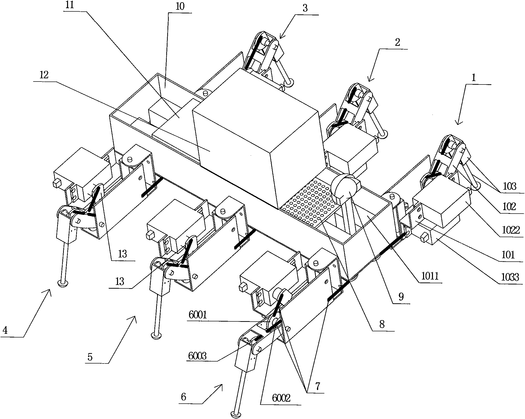
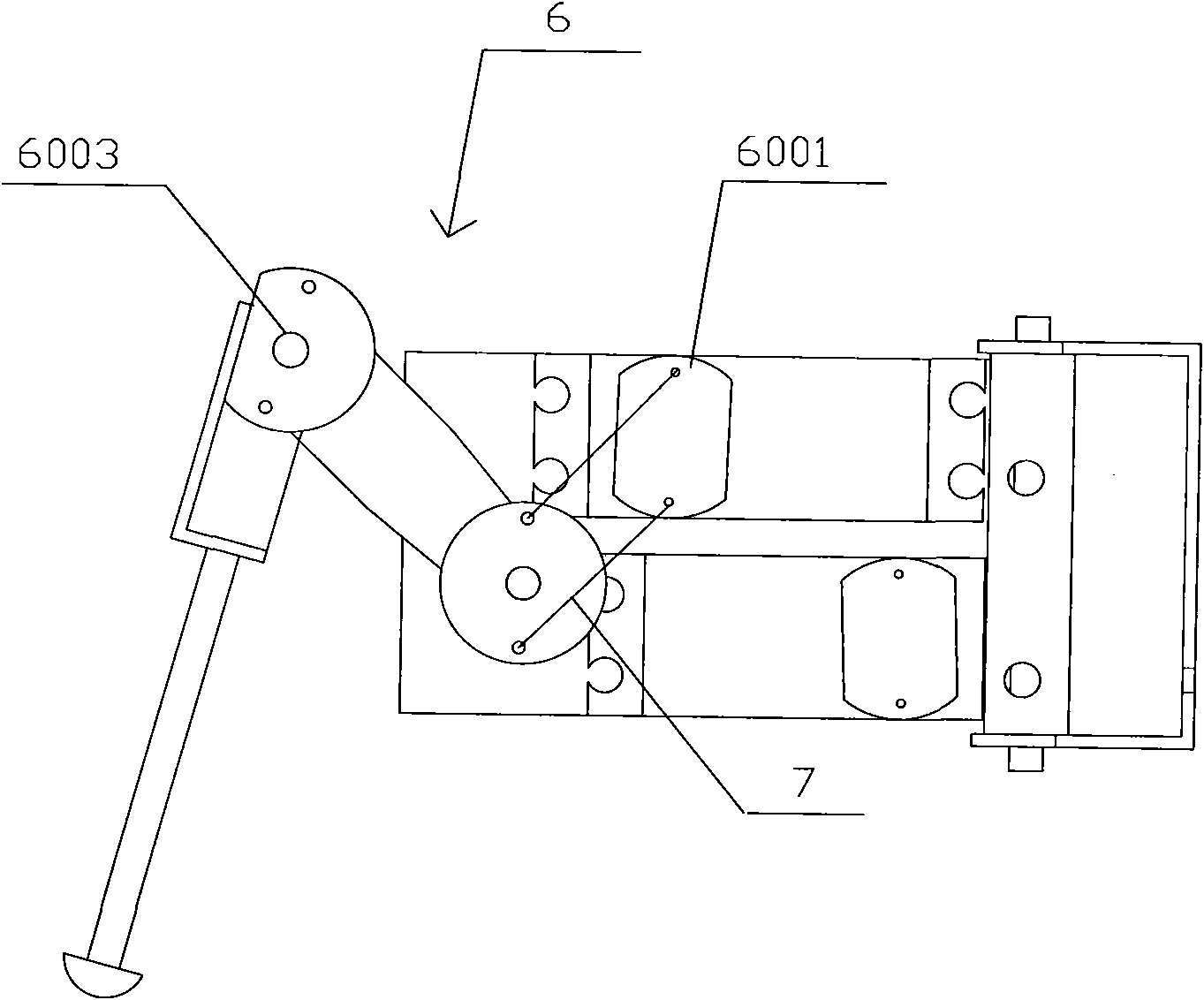
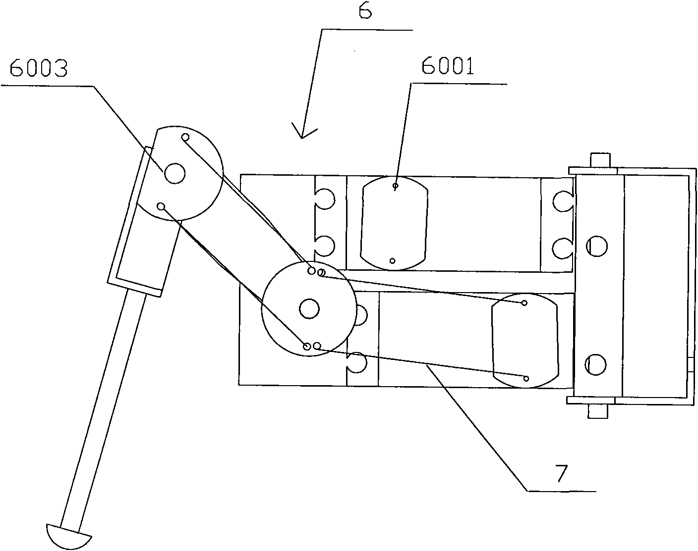
[0018] figure 1 is a structural schematic diagram of the present invention; Figure 4 It is a schematic diagram of the rope arrangement structure of the heel joint transmission of the present invention, see figure 1 and 4 , the rescue robot provided by the present invention includes a first leg 1, a second leg 2, a third leg 3, a fourth leg 4, a fifth leg 5, a sixth leg 6, a traction rope 7, a control unit 8, a camera 9, The torso 10, power supply 11, delivery unit 12, the first leg 1, the second leg 2, the third leg 3, the fourth leg 4, the fifth leg 5 and the sixth leg 6 are exactly the same, and the above six legs are composed of three joints Composition, the three joints are the base joint, femoral joint and tibial joint, with figure 1 Take the first leg 1 and the sixth leg 6 tha...


PUM


Abstract

The invention relates to a rescue robot, which adopts a traction rope as a driving mechanism of each joint and totally has 18 degrees of freedom, flexibly movement, stronger ability to adapt to uneven terrain and better obstacle capability. The rescue machine has small volume, light weight and stable operation, and is used in greatly dangerous disasters, especially in situations that people are anxious to ascertain the inside dangerous situations of disaster site but dare not or can not be close to or enter the disaster site.

Description

technical field [0001] The invention relates to the field of robot rescue, in particular to a hexapod bionic rescue robot with low cost and wide application range. Background technique [0002] Natural disasters such as earthquakes, fires, and floods seriously threaten human security and have aroused widespread concern. It is a challenging new field in robotics research to organically integrate multidisciplinary knowledge such as robotics, rescue operation technology, and disaster science to develop and develop disaster rescue devices for search and rescue. [0003] In recent years, especially after the "9.11" incident, many countries in the world have begun to develop various anti-terrorism explosion-proof robots, disaster rescue robots and other dangerous operation robots for disaster protection and rescue from the perspective of national security strategy. Hirose of Tokyo Institute of Technology in Japan has successively developed multiple series of rescue robot prototyp...

Claims


Application Information

Patent Timeline
IPC IPC(8): A62B99/00B62D57/032B25J11/00B25J19/00
Inventor 王宸曜陈峰谢连斌
Owner SHANGHAI MARITIME UNIVERSITY
Why Eureka
Try Eureka