

Control system of auxiliary robot of orthopedic surgery
A technology for orthopedic surgery and control systems, applied in the field of control systems in the field of electromechanical technology, can solve the problems that the mechanical structure does not realize six-degree-of-freedom movement and does not have independent control functions, and achieves high degrees of freedom, open structure, and convenient manipulation Effect
- Summary
- Abstract
- Description
- Claims
- Application Information
AI Technical Summary
Problems solved by technology
Method used
Image

Examples
Embodiment
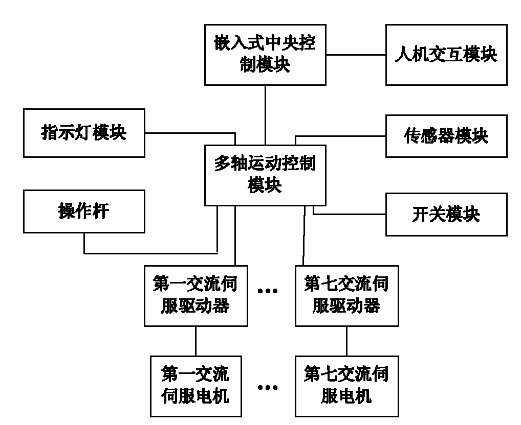
[0023] Such as figure 1 As shown, this embodiment includes: an embedded central control module, a multi-axis motion control module, 7 AC servo drivers, 7 AC servo motors, a human-computer interaction module, a sensor module, a switch module, an indicator module and a joystick, Among them: the embedded central control module is connected to the multi-axis motion control module to transmit motion planning information and other information transferred through the latter, the embedded central control module is connected to the human-computer interaction module to transmit image display information and user input information, multi-axis motion The control module is connected to the AC servo driver to transmit motor control information, the AC servo driver is connected to the AC servo motor to transmit motor drive and motor encoder information, the multi-axis motion control module is connected to the sensor module to transmit the limit position information of each motion joint and th...
PUM
 Abstract
Description
Claims
Application Information