
External mechanical induction type adjustable damping valve of oil-gas suspension

An oil-pneumatic suspension and inductive technology, applied in the direction of suspension, elastic suspension, mechanical equipment, etc., can solve the problems of high oil-pneumatic spring shock absorber, increase system cost, increase system pressure, etc., and achieve high reliability, The effect of simple structure and low cost

Inactive Publication Date: 2010-10-27
BEIJING INSTITUTE OF TECHNOLOGYGY
View PDF10 Cites 16 Cited by
  • Summary
  • Abstract
  • Description
  • Claims
  • Application Information

AI Technical Summary

Problems solved by technology

However, since this invention patent starts from the oil-gas shock absorber, there is such a problem that it must be provided with a special elastic element. If it is used as the elastic element itself, the part of the force originally borne by the elastic element will be completely absorbed by the oil-gas shock absorber. The spring shock absorber bears, which will inevitably increase the pressure of the system, and the piston area of ​​the oil-pneumatic spring shock absorber is determined by the piston area of ​​the modified shock absorber, which will be relatively small, which will make the pressure of the oil-pneumatic spring shock absorber very high. High, high requirements on the sealing of the system, and low reliability of the system
At the same time, this system requires special sensors and ECUs, which not only increases the cost of the system, but also reduces the reliability of the system.

Method used


Image

  • External mechanical induction type adjustable damping valve of oil-gas suspension
  • External mechanical induction type adjustable damping valve of oil-gas suspension
  • External mechanical induction type adjustable damping valve of oil-gas suspension

Examples


Embodiment Construction

[0028] The present invention is described in detail below in conjunction with accompanying drawing:

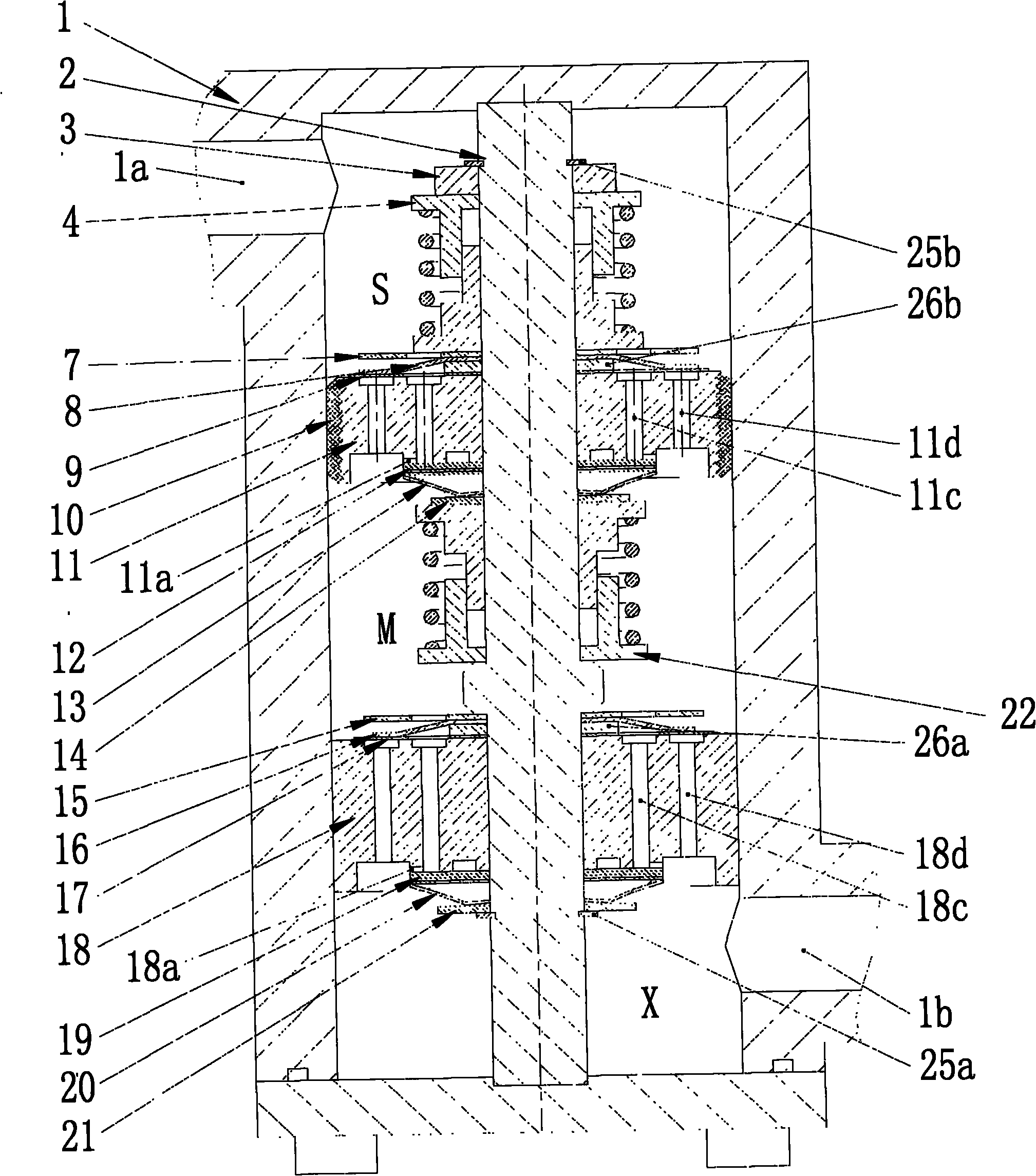
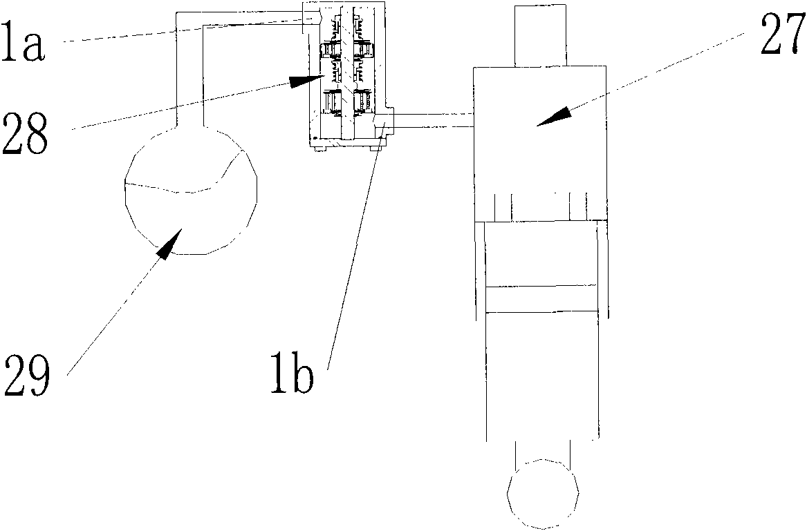
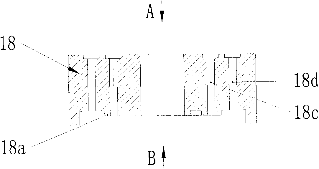
[0029] Such as figure 1 As shown, the external mechanical induction adjustable damping valve 28 of the oil and gas suspension includes a floating valve body 11 and a fixed valve body 18, the floating valve body 11 and the fixed valve body 18 are axially installed on On the upper installation rod 2, the fixed valve body 18 is fixed and limited by the positioning step on the installation rod 2 and the lower snap ring 25a; the floating valve body 11 is suspended on the compression limit seat assembly 4 and the extension limit seat assembly Between 22, the upward sliding displacement of the floating valve valve body 11 along the axis of the installation rod 2 is limited by the compression limit seat assembly 4, and the downward sliding displacement along the axis of the installation rod 2 is limited by the extension limit seat assembly 22; The valve body 11 and the fixed valve bo...


PUM


Abstract

The invention relates to an external mechanical induction type adjustable damping valve of an oil-gas suspension, which comprises an external mechanical induction type adjustable damping valve body, wherein an accumulator interface and an oil cylinder interface of the oil-gas suspension are arranged on the valve body; a mounting pole is arranged in the valve body, and a fixed valve and a floating valve are arranged on the periphery of the mounting pole; the floating valve is arranged between a compression limit spring and an extension limit spring in a suspended way; a fixed valve compression phase damping valve component and a fixed valve extension phase damping valve component are arranged at the two ends of the valve body of the floating valve respectively; a floating valve compression phase damping valve component and a floating valve extension phase damping valve component are arranged at the two ends of the valve body of the floating valve respectively; and a pre-stressing spring is arranged between a valve plate and a limit tray. The external mechanical induction type adjustable damping valve of the oil-gas suspension has the advantages that: the radiation is desirable; the outer diameter of a control valve element is small; the structure is simple; and the damping adjustment can be realized without electronic control system, and the reliability is high.

Description

Technical field: [0001] The invention relates to a damping element for an automobile suspension system, in particular to an external mechanical induction adjustable damping valve for an oil-air suspension used in the suspension system of a vehicle equipped with an oil-air suspension, and belongs to the field of mechanical structures. Background technique: [0002] Due to its nonlinear and gradually increasing stiffness characteristics, the oil-pneumatic spring has a good application prospect in special vehicles and off-road vehicles. It uses oil to transmit pressure, therefore, only need to add a proper damping device on the liquid path, the oil and gas spring can also be used as a damping element. Many oil-pneumatic suspensions do not design special damping elements, that is, the oil-pneumatic spring itself doubles as an elastic element and a damping element. The damping of this type of oil-pneumatic suspension mainly comes from two aspects. When the system reciprocates, d...

Claims


Application Information

Patent Timeline
Patent Type & Authority Applications(China)
IPC IPC(8): F16F9/34F16F9/50B60G17/08
Inventor 陈思忠王勋卢凡张军伟曾宇
Owner BEIJING INSTITUTE OF TECHNOLOGYGY
Learn More