
Inflatable elevating agitator tank

A mixing barrel, aerated technology, applied in the directions of dissolution, solid separation, wet separation, etc., can solve the problems of insufficiently improving minerals, increasing the height difference of the slurry in the mixing barrel, reducing production efficiency, etc., to improve the effect time and The effect of reaction speed, guarantee of continuous industrial production, reduction of quantity and cost

Inactive Publication Date: 2013-03-06
JIANGXI RARE EARTH & RARE METALS TUNGSTEN GRP HLDG CO LTD
View PDF1 Cites 0 Cited by
  • Summary
  • Abstract
  • Description
  • Claims
  • Application Information

AI Technical Summary

Problems solved by technology

Because the cantilever length of the main shaft of the mixing tank used in the prior art is limited to a certain extent, the lifting height difference in the mixing tank is relatively low, and the minerals passing through the mixing cannot be fully lifted, so the sand pump is usually used in series with the mixing tank to increase the stirring The height difference of the pulp in the barrel
[0003] In addition, after the rotation of the stirring impeller is lifted, the frivolous substances are lifted and overflowed out of the mixing tank, and heavier substances such as heavy metals and coarse-grained minerals will be deposited in the mixing tank, which increases the motor load of the mixing tank
If the deposition in the mixing tank is not cleaned in time, it will cause the shutdown of the self-protection motor, or more seriously, the motor will be burned
However, it is very inconvenient to clean up the deposits in the traditional stirring tank, and the entire assembly line needs to be shut down, and the deposits in the bottom tank must be manually cleared, and the production efficiency will also be reduced if the shutdown is stopped.

Method used


Image

  • Inflatable elevating agitator tank

Examples


Embodiment Construction

[0008] The present invention will be further described below in conjunction with drawings and embodiments.

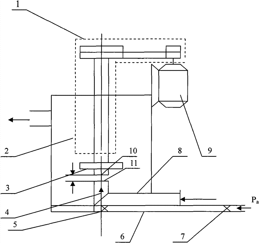
[0009] Such as figure 1 Shown is the cross-sectional view of the inflatable lifting mixing bucket provided by the present invention.

[0010] The inflatable lifting mixing drum provided by the present invention includes a motor 9 , a transmission device assembly 1 (shown by a dotted line in the figure), a lifting stirring impeller 3 and a stirring tank 2 . The above-mentioned transmission device assembly mainly includes a main shaft, one end of the main shaft has a main shaft pulley, and the other end is connected with the lifting agitating impeller 3 through the main shaft thread to form a vertical rotating shaft for lifting the agitating impeller 3; the motor 9 is provided with a motor pulley, which passes through the transmission belt Connect with the main shaft pulley of the transmission assembly. When the motor 9 works, the motor pulley on it drives the main shaf...


PUM


Abstract

The invention provides an inflatable elevating agitator tank comprising a motor, a drive assembly, an elevating agitator impeller, a agitator bath and a feeding pipe, wherein the motor drives the elevating agitator impeller installed on a vertical rotating shaft through the drive assembly to axially rotate vertical to the agitator bath in the agitator bath, and the lower end of the elevating agitator impeller is also provided with a feeding hole; the bottom inside the agitator bath is provided with a discharging hole of the feeding pipe, which is communicated with the outside through the feeding pipe; and the agitator bath is also provided with a gas filled pipe of which the air outlet end is communicated with the discharging hole of the feeding pipe and faces to the feeding hole of the elevating agitator impeller. The inflatable elevating agitator tank provided by the invention increases the elevating altitude difference in the agitator tank, improves the acting time and the reaction speed of minerals and drugs, enhances the selection effect of a flotation machine, overcomes the sediment phenomenon of coarse particles and heavy metals at the bottom of the agitator bath, and ensures the continuous industrial production.

Description

technical field [0001] The invention relates to a mineral processing machine, in particular to a mining lifting and mixing bucket. Background technique [0002] At present, the lifting and mixing barrel used in the mineral processing process is usually driven by the motor through the main shaft to rotate the lifting and stirring impeller to lift and stir the ore slurry in the mixing barrel. The lighter ore pulp is lifted and sent out for stirring barrel, and enter the next step of beneficiation process. The greater the lifting height difference in the mixing tank, the worse the effect of lifting the slurry. In order to improve its lifting and stirring effect, the rotating speed of the lifting mixing impeller in the mixing tank can be appropriately increased, and the length of the cantilever of the main shaft of the lifting mixing impeller should be lengthened, so that the lifting of the mixing impeller can lift the slurry higher. However, if the lower fulcrum of the main s...

Claims


Application Information

Patent Timeline
Patent Type & Authority Patents(China)
IPC IPC(8): B01F13/10B03B5/00
Inventor 揭才金文柏茂
Owner JIANGXI RARE EARTH & RARE METALS TUNGSTEN GRP HLDG CO LTD
Learn More