Method for vacuumizing cavity

A vacuum pumping and cavity technology, which is applied in the field of heating the getter material to generate steam to adsorb gas molecules, which can solve the problems of insignificant effect and increased cost, and achieve the effects of saving time, increasing production capacity, and reducing the time for vacuuming

Active Publication Date: 2010-11-03
MOSEL VITELIC INC
View PDF0 Cites 4 Cited by
  • Summary
  • Abstract
  • Description
  • Claims
  • Application Information

AI Technical Summary

Problems solved by technology

The existing improvement method is to increase the power of the pump, however, this method will increase the cost, and the effect is not significant

Method used


Image

  • Method for vacuumizing cavity
  • Method for vacuumizing cavity

Examples


Embodiment Construction

[0037] The foregoing and other technical contents, features and effects of the present invention will be clearly presented in the following detailed description of preferred embodiments with reference to the accompanying drawings.

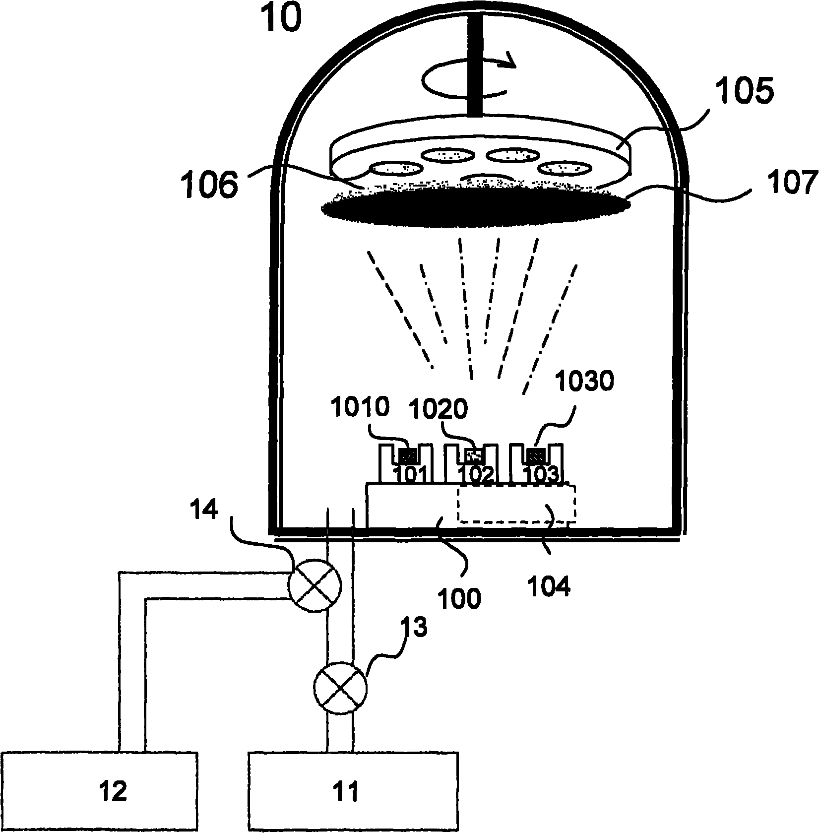
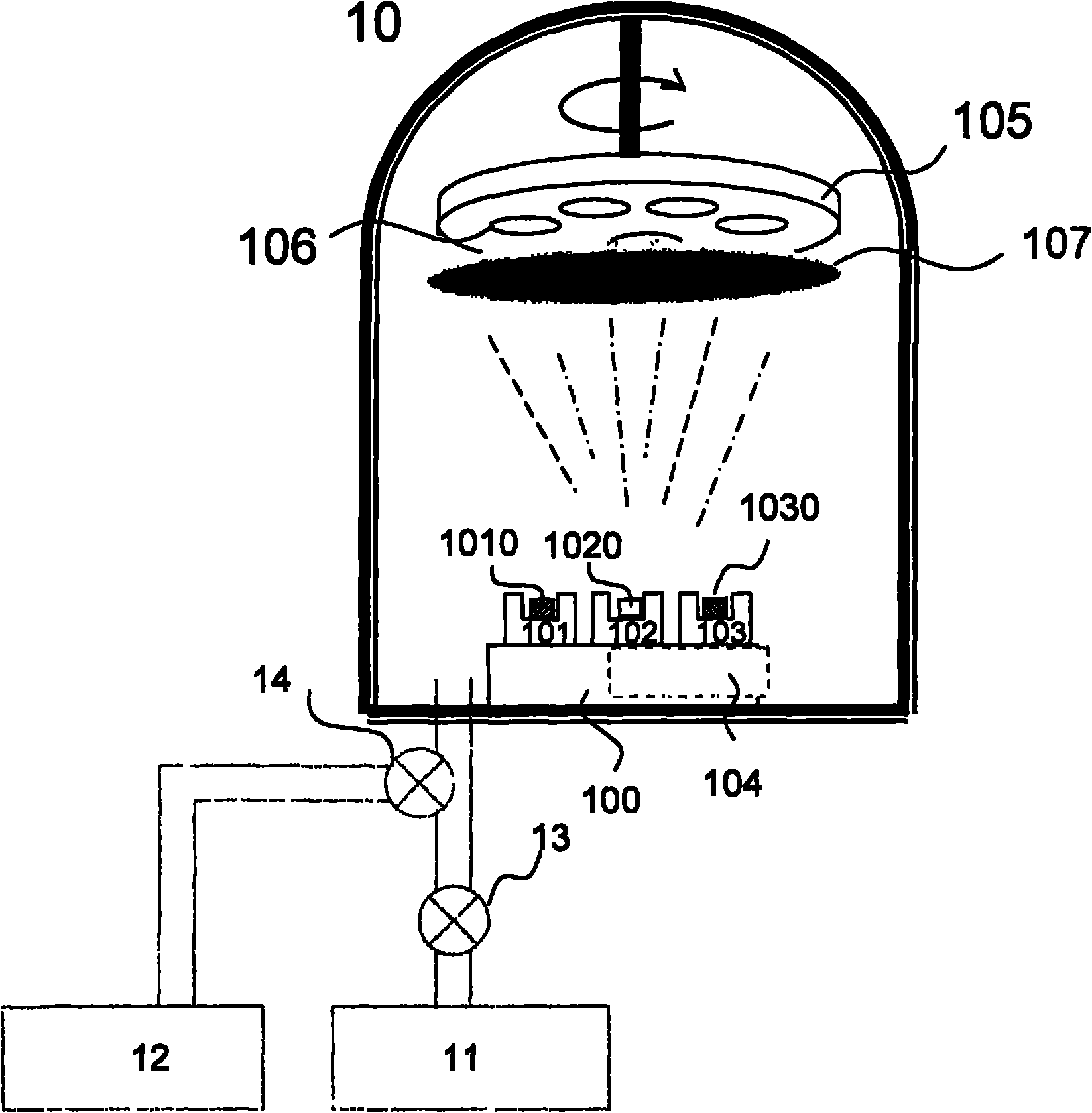
[0038] The invention provides a method for evacuating a cavity for film deposition in a semiconductor manufacturing process, which can save the time for evacuating the cavity. figure 1 Shown is the application of an embodiment of the present invention. Firstly, a thin film deposition chamber 10 for semiconductor manufacturing is provided. There is a carrying platform 100 in the chamber 10, which is used to carry several crucibles (crucible) 101-103, wherein a crucible ( Crucible) 102 places a getter material 1020, and this getter material is a titanium block in the embodiment of the present invention, and the getter material 1020 is heated by a heater 104 to generate steam during the pumping process to capture the residual gas in the cavity Molecul...


PUM


Abstract

The invention relates to a method for vacuumizing a semiconductor process thin film deposition cavity, which comprises the following steps of: providing a semiconductor process thin film deposition cavity, carrying out air exhaust on the semiconductor process thin film deposition cavity by using a low vacuum pump, carrying out second stage air exhaust by using a high vacuum pump to adjust a baffle plate to block a wafer, heating an air absorbing material in a crucible by using a heater to generate steam used for capturing residual gas in the cavity to form a compound, deposing the compound on the baffle plate until reaching the target vacuum degree, stopping heating the air absorbing material, and opening the adjustable baffle plate for carrying out the next procedure.

Description

technical field [0001] The invention relates to a method for evacuating a deposition chamber of a semiconductor manufacturing process, in particular to a method for generating vapor by heating a getter material to adsorb gas molecules. Background technique [0002] In the general semiconductor or thin film process, it must be carried out in a relatively high vacuum environment, usually first let the vacuum in the deposition chamber reach a certain level (about 10 -5 torr), the subsequent thin film deposition process can be continued. It is a common technology to use vacuum equipment to meet this requirement. Whether the current thin film manufacturing process utilizes CVD (Chemical Vapor Deposition) or PVD (Physical Vapor Deposition), vacuum equipment must be used. [0003] Evacuate the vacuum in the chamber from atmospheric pressure (760torr) to high vacuum (10 -3 ~10 -5 torr) is usually divided into two stages to pump air. First, use mechanical pumps, dry pumps or low ...

Claims


Application Information

Patent Timeline
IPC IPC(8): H01L21/00C23C14/30
Inventor 林俊德邱志欣杨环隆林玉婷黄继毅
Owner MOSEL VITELIC INC
Why Eureka
Try Eureka