Multi-chamber continuous optical coating machine
An optical coating machine, coating machine technology, applied in the direction of sputtering coating, vacuum evaporation coating, ion implantation coating, etc., can solve the problem of large error, to reduce the time of vacuuming, high degree of automation, improve coating The effect of work efficiency
- Summary
- Abstract
- Description
- Claims
- Application Information
AI Technical Summary
Problems solved by technology
Method used
Image
Examples
Embodiment 1
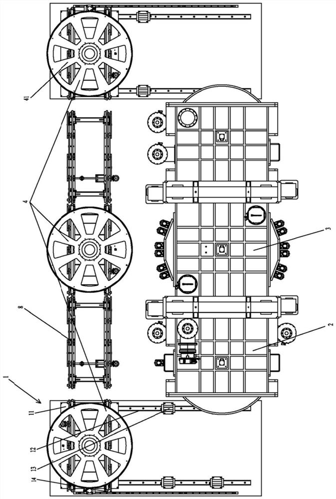
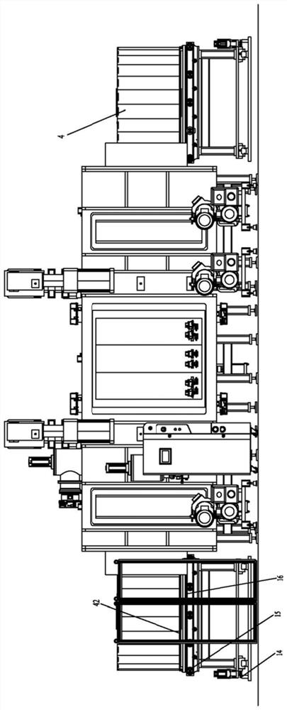
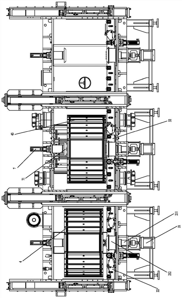
[0040] Figure 1 to Figure 4 The first embodiment of the multi-chamber continuous optical coating machine of the present invention is shown. In this embodiment, the workpiece turret 4 can only revolve, but cannot rotate.
[0041] In this embodiment, the coating machine includes a running mechanism, at least one transfer unit, at least one antechamber 2, and at least one coating chamber 3, and the coating piece is arranged on a workpiece turret 4, and the transfer unit and the antechamber 2 The front chamber 2 is connected with the coating chamber 3, the transfer part on one side, the front chamber 2 and the coating chamber 3 form a coating channel for the plated parts, and the front chamber 2 and the other transfer part on the other side form a film outlet aisle. The front chamber 2 and the coating chamber 3 are provided with a vacuum device 5 independently, and the front chamber 2 and the coating chamber 3 are separate sealed chambers, and the workpiece turret 4 rotates in t...
Embodiment 2
[0056] Figure 4 The second embodiment of the multi-chamber continuous optical coating machine of the present invention is shown. In this embodiment, the structure of the transmission part, the front chamber, and the preparation part is the same as that of Embodiment 1, the difference is that the workpiece turret 4 can revolve and rotate, The running mechanism is provided with an autorotation assembly 9 .
[0057] In this embodiment, the workpiece turret 4 includes a top plate 41, a bottom plate 42, a plurality of rotation frames, and a plurality of rotation shafts 44. The rotation shafts 44 are arranged between the top plate 41 and the bottom plate 42 and arranged along the circumferential direction. Each rotation frame is installed on an axis of rotation 44 . Bearings are provided at the connection between the rotation shaft 44 and the top plate 41 and the bottom plate 42 , and the rotation frame is evenly arranged along the circumference of the top plate 41 and the bottom ...
PUM
 Abstract
Description
Claims
Application Information
 - R&D
- Intellectual Property
- Life Sciences
- Materials
- Tech Scout
- Unparalleled Data Quality
- Higher Quality Content
- 60% Fewer Hallucinations
Browse by: Latest US Patents, China's latest patents, Technical Efficacy Thesaurus, Application Domain, Technology Topic, Popular Technical Reports.
© 2025 PatSnap. All rights reserved.Legal|Privacy policy|Modern Slavery Act Transparency Statement|Sitemap|About US| Contact US: help@patsnap.com


