
Regenerative electric energy feedback method for elevator and device thereof

An electric energy feedback and elevator technology, applied in the field of elevators and tower cranes, can solve the problems of reducing maintenance, maintenance times, adverse motor operation, equipment component damage, etc., and achieve the effect of improving service life, improving braking effect, and saving energy.

Inactive Publication Date: 2010-11-10
宁波倍加福电子科技有限公司
View PDF3 Cites 19 Cited by
  • Summary
  • Abstract
  • Description
  • Claims
  • Application Information

AI Technical Summary

Problems solved by technology

[0004] The invention mainly solves the technical problem that the electric energy generated by the motor on the original tower crane and elevator is consumed through the high-power resistor during the braking process, which is not conducive to the operation of the motor, will cause harm to the equipment components, and waste a large amount of electric energy. Provide a method and device for feeding back regenerative electric energy of an elevator, which can process the electric energy generated by the motor on the tower crane and the elevator during the braking process and then feed it back to the power grid, so as to effectively use this part of electric energy to achieve the purpose of saving energy, and It also plays a good role in protecting the equipment components, which is beneficial to the operation of the motor and reduces the number of repairs and maintenance

Method used


Image

  • Regenerative electric energy feedback method for elevator and device thereof
  • Regenerative electric energy feedback method for elevator and device thereof
  • Regenerative electric energy feedback method for elevator and device thereof

Examples


Embodiment 1

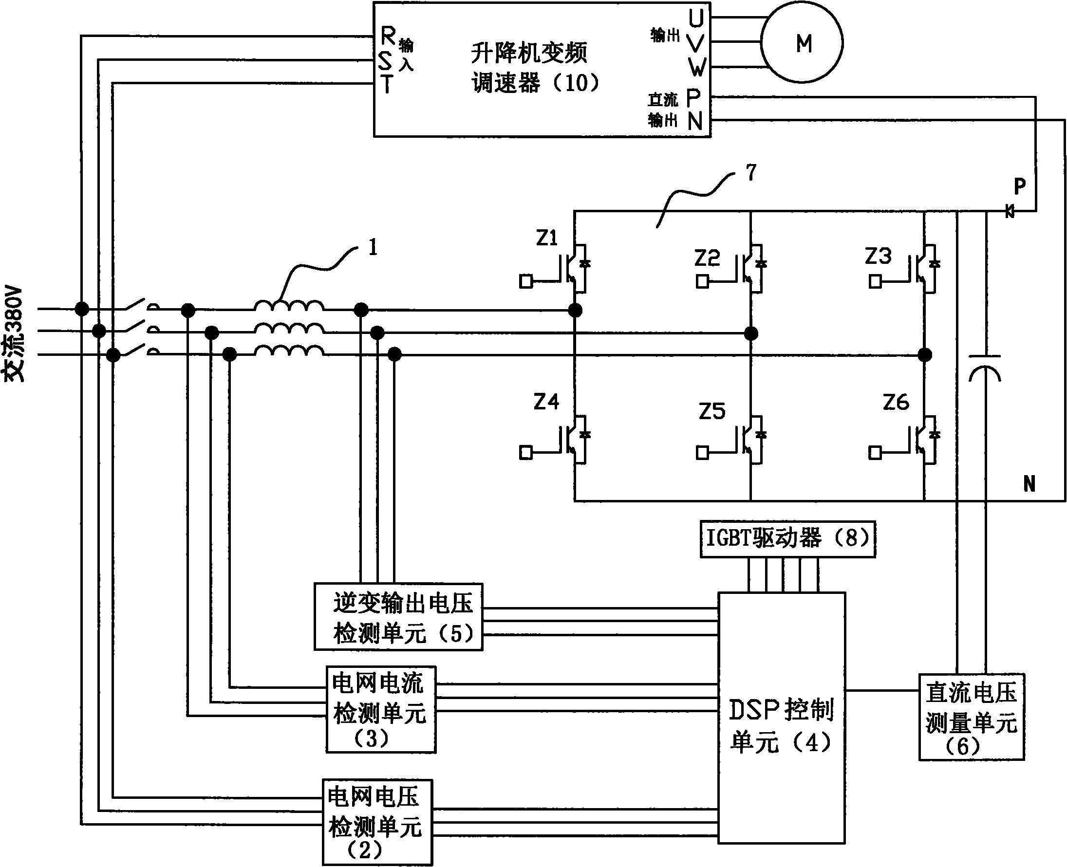
[0018] Embodiment 1: The elevator regenerative electric energy feedback device of this embodiment, such as figure 1 As shown, it includes an inverter composed of an IGBT controllable bridge circuit 7 connected to a reactor 1, a grid voltage detection unit 2, a grid current detection unit 3, a DSP control unit 4, a DC voltage measurement unit 6, and an inverter output voltage Detection unit 5. The DC output terminal of the elevator frequency converter 10 is connected to the DC terminal of the IGBT controllable bridge circuit 7 , and the output voltage of the inverter is integrated into the grid for the elevator frequency converter 10 to work through the reactor 1 . The input end of the grid voltage detection unit 2 and the input end of the grid current detection unit 3 are respectively connected to the power grid for the frequency conversion speed regulator 10 of the elevator, and the output end of the grid voltage detection unit 2 and the output end of the grid current detecti...


PUM


Abstract

The invention relates to a regenerative power energy feedback method for an elevator and a device thereof. The device comprises an inverter, a network voltage detection unit, a network current detection unit, a DSP control unit and a direct current voltage measuring unit, wherein the inverter is formed by connecting an IGBC controllable bridge circuit with an electric reactor; the direct current output end of the variable-frequence governor of the elevator is connected with the direct current end of the IGBC controllable bridge circuit; the output voltage of the inverter is merged into a power network supplying the power for the variable-frequence governor of the elevator to work through the electric reactor; the input end of the network voltage detection unit and the input end of the network current detection unit are respectively connected to the power network supplying power for the variable-frequence governor of the elevator to work; the output end of the network voltage detection unit and the output end of the network current detection unit are respectively connected with the DSP control unit; the DSP control unit is connected with the control end of the IGBC controllable bridge circuit through an IGBT driver; and the direct current output of the variable-frequence governor of the elevator is connected with the DSP control unit through the direct current voltage detection unit.

Description

technical field [0001] The invention relates to the field of tower cranes and elevators, in particular to a method and device for feeding back regenerative electric energy of elevators, which not only facilitates the safe operation of tower cranes and elevator equipment, but also achieves the purpose of energy saving and emission reduction. Background technique [0002] The motors on tower cranes and elevators will work in the power generation state during the braking process, and the generated electric energy will generate a pumped DC voltage through the braking working state of the frequency converter. This voltage will destroy the working state of the frequency converter and cause damage to equipment components. harm. [0003] The electric energy generated when the motor brakes is rectified and converted into DC and stored in a large capacitor, but excessive charge accumulation will cause a voltage rise, which will affect the normal operation of the inverter. For this re...

Claims


Application Information

Patent Timeline
Patent Type & Authority Applications(China)
IPC IPC(8): H02J3/38G01R19/00
Inventor 戴旭阳孟明方飞鸽
Owner 宁波倍加福电子科技有限公司
Learn More