Electrifying startup circuit and electrifying startup method thereof

An electric starting and circuit technology, applied in circuits, electrical components, electronic switches, etc., can solve the problems of component damage, large area occupied by discrete components, large inrush current, etc., to avoid overshoot and reduce the number of , the effect of reducing the volume

Active Publication Date: 2010-11-10
SILERGY SEMICON TECH (HANGZHOU) CO LTD
View PDF2 Cites 49 Cited by
  • Summary
  • Abstract
  • Description
  • Claims
  • Application Information

AI Technical Summary

Problems solved by technology

[0007] (1) The number of discrete components required is large; the area occupied by each discrete component is relatively large;
[0008] (2) The power-on delay is controlled by a delay circuit composed of a resistor and a capacitor. Due to the discreteness of the gate threshold voltage of the power switch tube M, the delay control is inaccurate;
[0009] (3) When the power is turned on, when the switching device is turned on instantaneously or the enabling start signal EN suddenly increases to a large value, this will cause a large surge current, which will give the components in the subsequent power supply chip cause damage, or the surge current may cause the input power voltage to drop enough to cause instantaneous power failure of other power equipment using the same input power
[0010] Visible, using figure 1 In the implementation scheme shown, the power-on delay control is not accurate enough, and because there is no current limiting protection function, it brings hidden dangers to the normal operation of the subsequent circuit

Method used


Image

  • Electrifying startup circuit and electrifying startup method thereof
  • Electrifying startup circuit and electrifying startup method thereof
  • Electrifying startup circuit and electrifying startup method thereof

Examples


Embodiment Construction

[0067] Preferred embodiments of the present invention are described in detail below with reference to the accompanying drawings, but the present invention is not limited to these embodiments. The present invention covers any alternatives, modifications, equivalent methods and schemes made on the spirit and scope of the present invention. In order to provide the public with a thorough understanding of the present invention, specific details are set forth in the following preferred embodiments of the present invention, but those skilled in the art can fully understand the present invention without the description of these details.

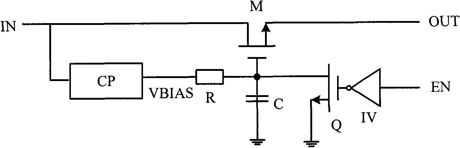
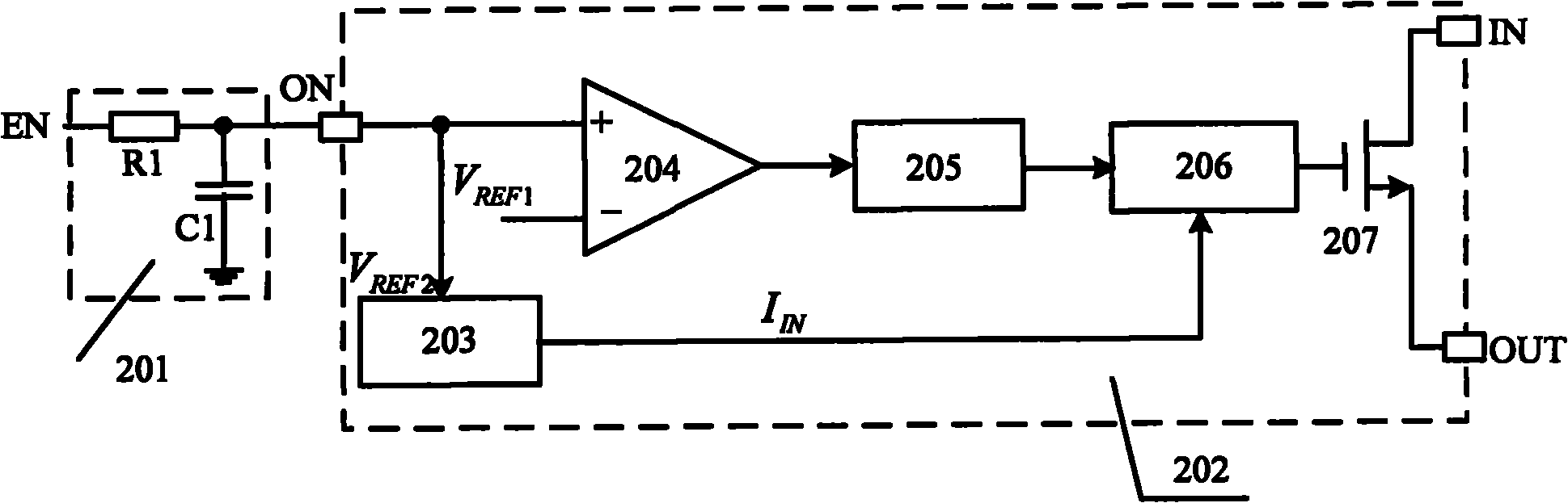
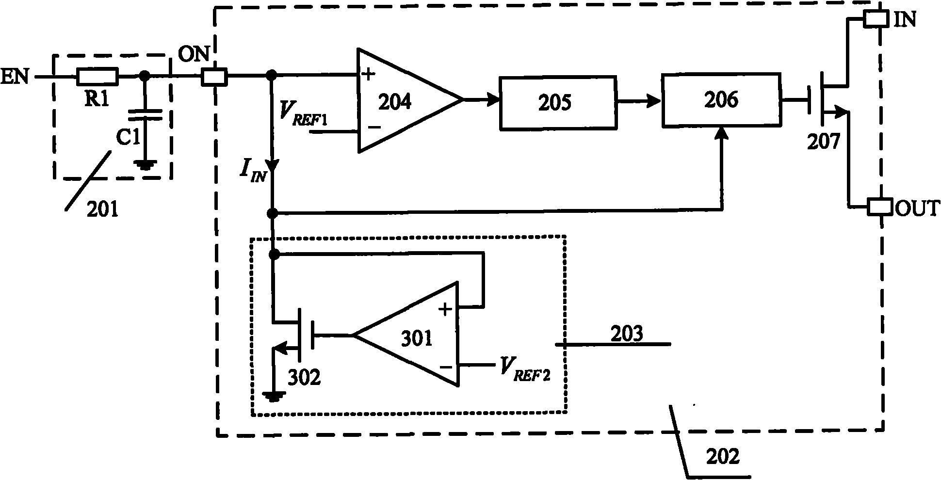
[0068] refer to figure 2 , shows a functional block diagram of the first embodiment of the power-on start-up circuit according to the present invention. It is composed of a delay circuit 201 and a control chip 202. The control chip 202 has at least three pins: a multiplexing pin ON, an input pin IN and an output pin OUT. Wherein, the control chip ...


PUM


Abstract

The invention relates to an electrifying startup circuit and an electrifying startup method thereof. The electrifying startup circuit simultaneously realizes an electrifying time-delay control function and a current limiting protection function by using a multiplexing pin of a chip in which a power switching tube and a control circuit are integrated and using an external RC time-delay circuit, so the electrifying startup circuit starts to work after a certain time delay. A control chip is provided with at least three pins such as the multiplexing pin, an input pin and an output pin, wherein the multiplexing pin is connected with the RC time-delay circuit; the input pin is connected with an input voltage source; the output of the output pin is used for supplying power to lower level connected equipment; a first reference voltage source is arranged in the control chip; the output pin outputs a voltage signal; and the delay time is determined by first capacitance and a first reference voltage. As the electrifying time-delay control and the output current limiting protection share the same multiplexing pin of the integrated control chip, the number of pins of the chip is reduced, and the volume of the chip is reduced; and an output voltage of the electrifying startup circuit is slowly risen according to a certain rising slope, so that damage to subsequent circuits or influence on normal work of the subsequent circuits due to the overshoot of the output voltage in the electrifying process is avoided.

Description

technical field [0001] The invention relates to a power-on start-up circuit and a power-on start-up method of a power supply, belonging to an electronic circuit. Background technique [0002] With the continuous growth of portable electronic products in the fields of communications, computers and consumer electronics, the demand for power management ICs is also on the rise, such as typical DC / DC DC-DC switching power supplies, AC / DC switching power supplies, etc. more and more widely applied. As the electronic system tends to become more complex, the system puts forward higher requirements on the power-on sequence and power-on stability of the power supply voltage. [0003] In a complex electronic system, such as a notebook computer, there are multiple sets of power supplies. At the same time, the output voltage of each group of power supply may supply power to multiple loads at the same time. The load here is usually a digital chip in an electronic system. The power sup...

Claims


Application Information

Patent Timeline
Patent Type & Authority Applications(China)
IPC IPC(8): H02M1/36
CPCH02M1/36H02M2001/0025G05F1/10H03K17/166H03K17/0822H03K17/223H02M1/32H02M1/0025
Inventor 陈伟
Owner SILERGY SEMICON TECH (HANGZHOU) CO LTD
Why Eureka
Try Eureka