Novel low-resistance injector

A low-resistance syringe, a new type of technology, applied in syringes, infusion sets, etc., can solve problems such as failure to meet industry standards, inability to effectively reduce frictional resistance between the piston and the cylinder wall, and inability to large-scale mass production.

Inactive Publication Date: 2010-11-17
余利荣
View PDF7 Cites 7 Cited by
  • Summary
  • Abstract
  • Description
  • Claims
  • Application Information

AI Technical Summary

Problems solved by technology

Another example: Chinese patent 95193831.2 (publication number: CN1152882A, publication date: June 25, 1997) discloses a "low-resistance syringe", the piston rod of which can deform the piston so that the radial wall is drawn from the cylinder The wall is pulled apart to reduce the friction between the piston and the barrel wall, but these syringes cannot automatically adjust the sealing degree between the piston and the barrel wall with the change of the pressure in the barrel, and cannot effectively reduce the frictional resistance between the piston and the barrel wall , can not achieve better results
The name applied by the inventor is "low resistance syringe" (patent number: 200510060714.2). Compared with the existing syringe piston, this syringe has higher sensitivity. Once the pressure in the cylinder changes, the sealing ring will squeeze open and expand. Or the rebound is reduced, which not only ensures the seal between the sealing ring and the inner wall of the injection cylinder without leakage, but also reduces the frictional resistance between the sealing ring and the inner wall of the injection cylinder due to extrusion, so as to achieve the purpose of low resistance and strong sealing. However, this kind of syringe has high requirements on mold precision, and the production process of rubber vulcanization is relatively difficult. When the friction resistance is 0.1 (Newton), the failure rate of the product is more than 1 / 10,000, which cannot reach the industry standard and cannot be mass-produced on a large scale. Production

Method used


Image

  • Novel low-resistance injector
  • Novel low-resistance injector
  • Novel low-resistance injector

Examples


Embodiment Construction

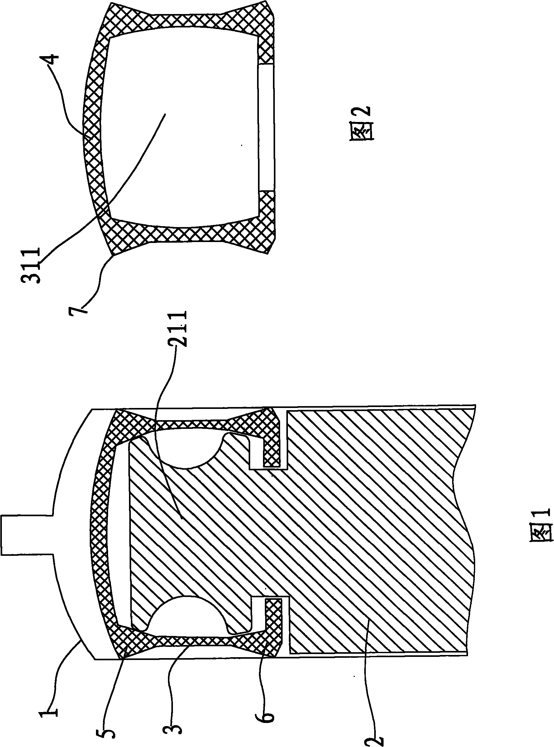
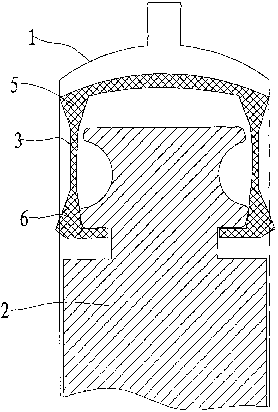
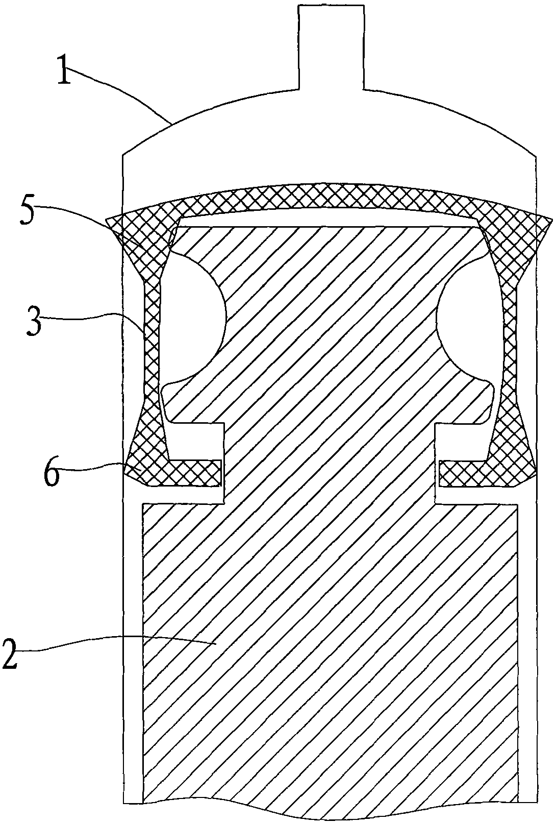
[0017] see figure 1 , a new type of low-resistance syringe, including a syringe (1), a push rod (2), and a rubber stopper (3), the push rod (2) is composed of a body and an installation head (211) for installing the rubber stopper, and the rubber stopper (3) There is a cavity (311) for accommodating the installation head (211). The cavity (311) of the rubber plug (3) is large in the middle and small at both ends along the axial direction of the push rod (2). See figure 2 ,Depend on figure 2 It can be seen that the longitudinal section (along the axial direction of the push rod) of the rubber plug cavity (311) is a waist circle with a large center and a small two ends. The diameter of the upper and lower ends of the installation head (211) is slightly larger than the diameter of the two ends of the cavity (311). Space, the rubber plug (3) can slide back and forth relative to the push rod along the axial direction of the push rod, the height of the rubber plug cavity (311) i...


PUM


Abstract

The invention relates to a novel low-resistance injector. The novel low-resistance injector comprises a syringe, a push rod and a rubber plug, wherein the push rod consists of a main body and a mounting head which is used for mounting the rubber plug; a cavity for accommodating the mounting head is reserved in the rubber plug; the cavity of the rubber plug has a big middle part and two small ends along the axial direction of the push rod; the diameters of the upper and lower heads of the mounting head are a little bigger than those of the two heads of the cavity; after the rubber plug is arranged on the push rod, space is reserved between the mounting head and the rubber plug in the axial direction, so that the rubber plug can slide backwards and forwards relative to the push rod along the axial direction of the push rod; the top part of the rubber top slightly arches upwards to form a hogback; two sealing rings are integrally formed on the outer circumference of the rubber plug; and the section of each sealing ring has a triangular shape, so that the four corners on the outside of the longitudinal section of the rubber plug have angular shapes. The injector adopts the structure and the frictional resistance is reduced to 0.05 Newton, so that the aims of low resistance and high sealing property are fulfilled. The practice shows that the low-resistance injector products have the advantages of simple production process, reject ratio lower than 1 / 10,000 and suitability for large-scale batch production.

Description

technical field [0001] The invention relates to a medical syringe, in particular to a low-resistance syringe capable of reducing the frictional resistance between the inner wall of the syringe barrel and the sliding piston inside. Background technique [0002] Syringes are an indispensable tool in medical treatment, especially in the field of anesthesia punctures. The known epidural anesthesia puncture kits still use glass syringes, and their injection cylinders are made of glass. The disadvantages of this glass syringe It is easy to break during transportation. Because the push rod is frosted, the glass shavings cannot be cleaned thoroughly, and the copper core is out of round, which will cause liquid leakage, resulting in unsatisfactory use. If the injection cylinder is replaced by other materials, in order to prevent To obtain a good leak-proof sealing effect, the piston must press against the inner wall of the cylinder. If the interference between the cylinder and the pi...

Claims


Application Information

Patent Timeline
IPC IPC(8): A61M5/178A61M5/31
Inventor 余利荣
Owner 余利荣
Why Eureka
Try Eureka