Electric power tool

A technology of electric tools and electric motors, applied in the direction of manufacturing tools, electric components, electrical components, etc., can solve the problems of large power loss, heat damage, damage, etc., and achieve the effect of shortening the installation space

Active Publication Date: 2010-11-17
HITACHI KOKI CO LTD
View PDF8 Cites 14 Cited by
  • Summary
  • Abstract
  • Description
  • Claims
  • Application Information

AI Technical Summary

Problems solved by technology

[0005] In the brushless motor, since a large current is passed to the semiconductor switching element (power transistor) mounted on the inverter circuit board, the power loss is large, and thus the heat generation of the semiconductor switching element increases.
If the amount o

Method used


Image

  • Electric power tool
  • Electric power tool
  • Electric power tool

Examples


Embodiment Construction

[0045] Hereinafter, embodiments of the present invention will be described in detail based on the drawings. In addition, in all the drawings for explaining the embodiment, the members or elements having the same functions are assigned the same reference numerals, and overlapping descriptions are omitted.

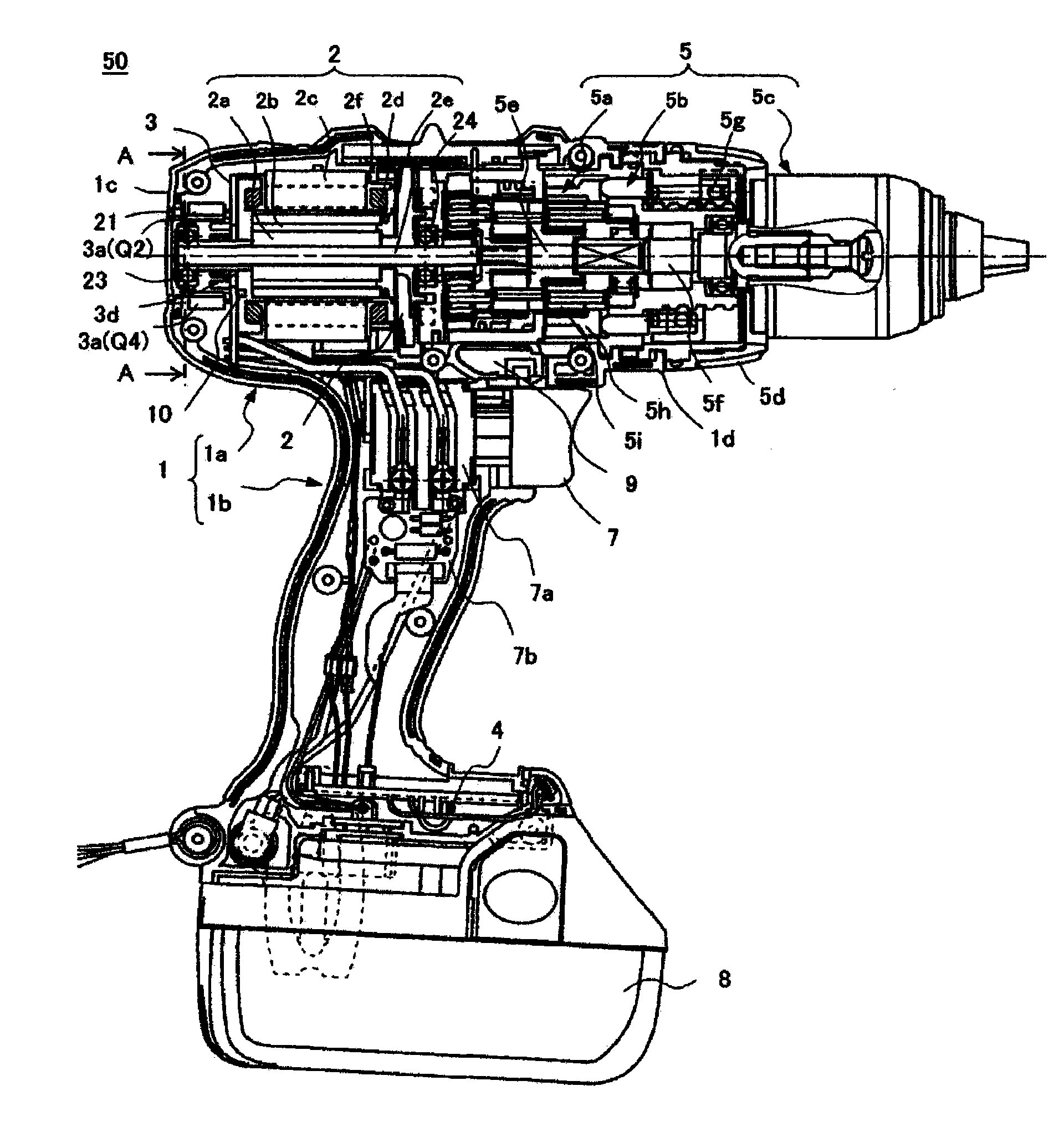
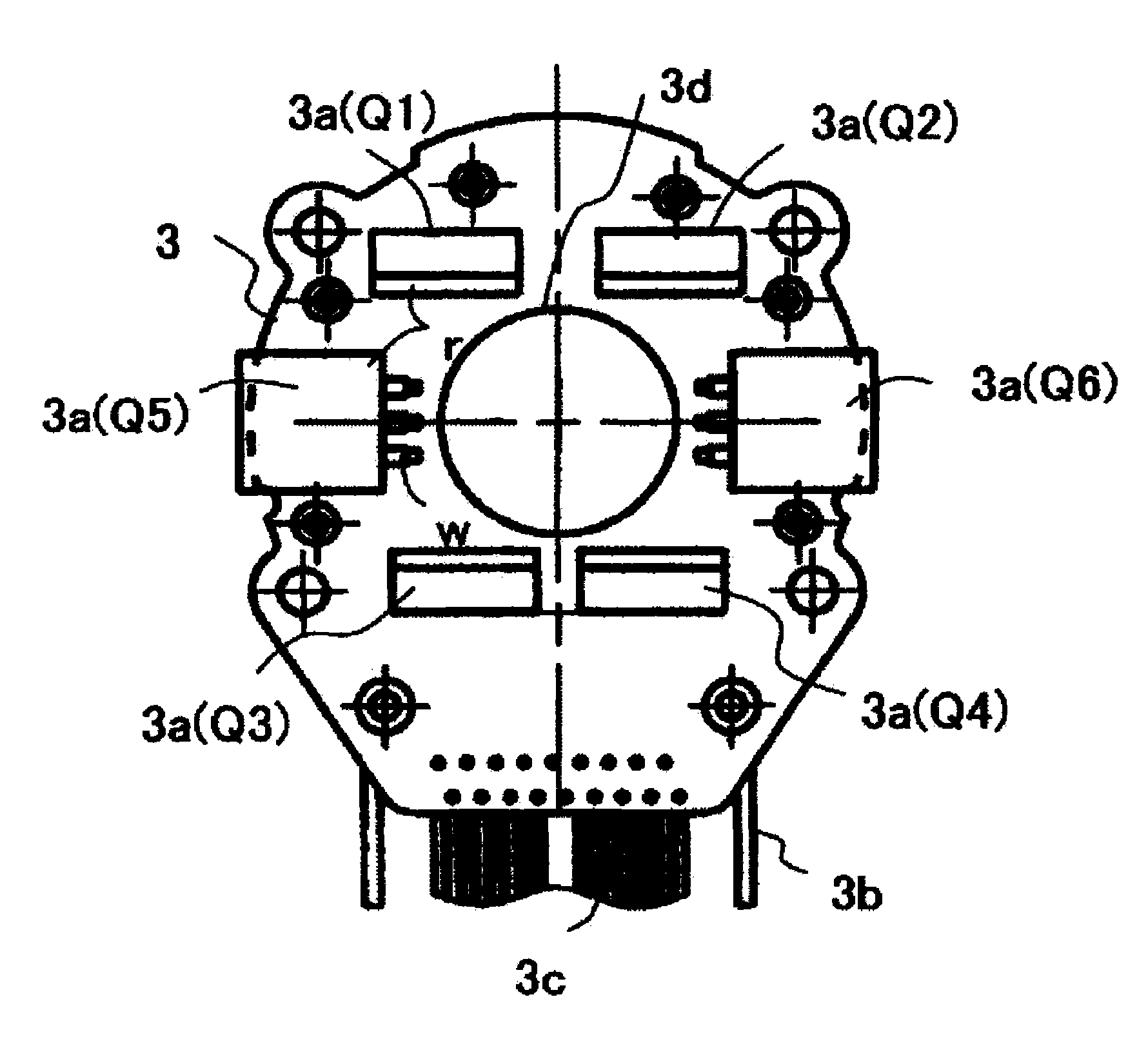
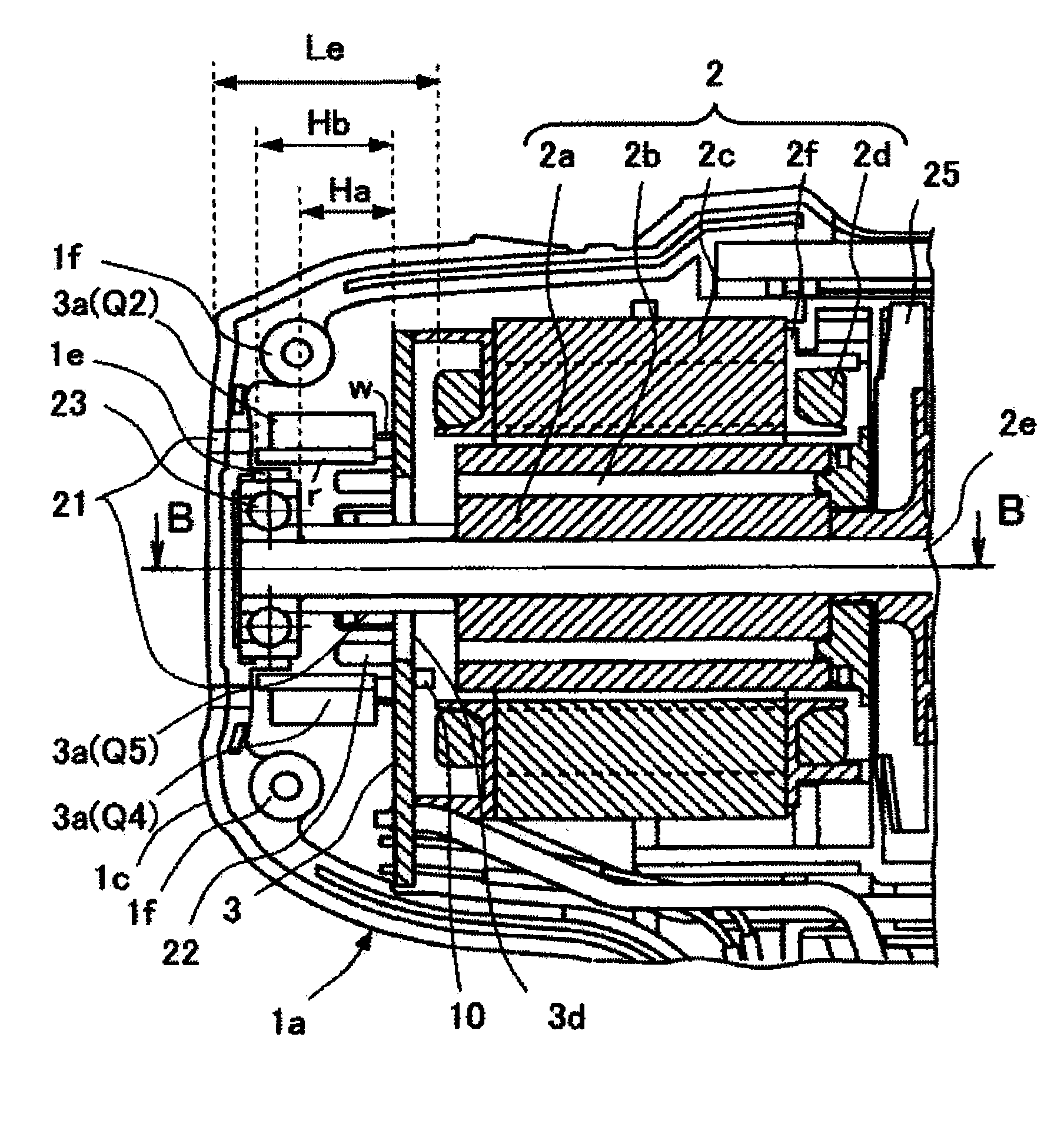
[0046] figure 1 It is a cross-sectional part showing the overall structure of the internal power type electric screwdriver drill according to one embodiment of the present invention, figure 2 is directed at figure 1 The top view of the inverter circuit substrate viewed from the A-A line of the driver electric drill shown, image 3 yes figure 1 The enlarged structural diagram of the key parts of the screwdriver electric drill shown, Figure 4 yes image 3 The B-B line sectional view of the enlarged structural diagram of the main part shown, Figure 5 From Figure 4 The top view of the inverter circuit substrate observed by the D-D line, Figure 6 yes figure 1 Functi...


PUM


Abstract

An electric power tool includes: a motor including a motor shaft; a tip tool driven by the motor; a housing that houses the motor; a switching element for driving the motor; and a bearing that can retain the motor shaft. The switching element is provided so as to overlap with the bearing in a direction of the motor shaft inside the housing.

Description

[0001] This application claims priority from Japanese Patent Application No. 2009-114609 filed on May 11, 2009, the disclosure of which is incorporated herein by reference. technical field [0002] The invention relates to an electric tool with a brushless motor as a driving source. In addition to tools for fastening and opening holes such as impact drivers, driver drills, vibratory drills, and electric hammer drills, the present invention can also be applied to other tools using brushless motors such as circular saws and wire saws. electrical tools. Background technique [0003] For example, as disclosed in Patent Document 1 below, there is known an electric power tool that uses a brushless motor (brushless DC motor) as a drive source. Compared with commutator motors, brushless motors have higher efficiency. When brushless motors are used in internal power tools that use rechargeable batteries (battery packs), the operating time of the power tool per charge is equal to It...

Claims


Application Information

Patent Timeline
IPC IPC(8): B25F5/00B25F5/02
CPCH02K11/0073H02K2211/03B25F5/008H02K7/145H02K11/33
Inventor 东海林润一武田岳史小室义广喜岛裕司川端康生
Owner HITACHI KOKI CO LTD
Why Eureka
Try Eureka