
Display apparatus

A display device and pixel circuit technology, applied to static indicators, instruments, electrical components, etc., to achieve the effect of cost reduction

Active Publication Date: 2010-11-17
JOLED INC
View PDF7 Cites 15 Cited by
  • Summary
  • Abstract
  • Description
  • Claims
  • Application Information

AI Technical Summary

Problems solved by technology

In other words, proper level control is no longer possible

Method used


Image

  • Display apparatus
  • Display apparatus
  • Display apparatus

Examples


Embodiment Construction

[0064] Hereinafter, preferred embodiments of the present invention will be described in detail in the following order with reference to the accompanying drawings.

[0065] 1. Configuration of Display Device and Pixel Circuit

[0066] 2. Double gate structure

[0067] 3. Pixel circuit operation for threshold correction and mobility correction

[0068] 1. Configuration of Display Device and Pixel Circuit

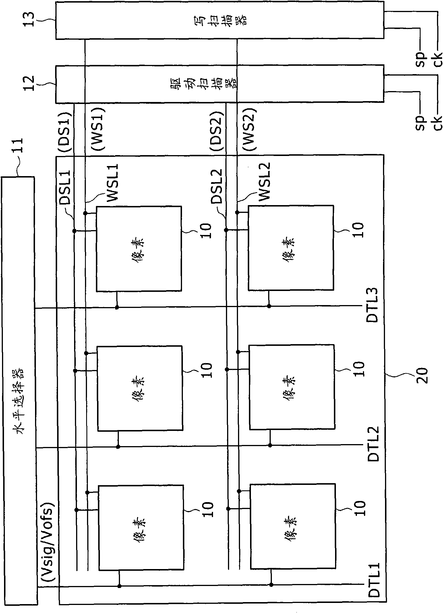
[0069] figure 1 The configuration of an organic EL display device to which the present invention is applied is shown.

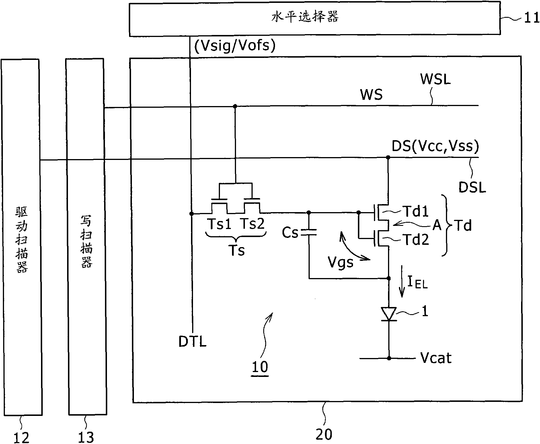
[0070] refer to figure 1 , the organic EL display device shown includes a plurality of pixel circuits 10, which use organic EL elements as their light emitting elements, and are driven to emit light according to an active matrix method.

[0071] Specifically, the organic EL display device includes a pixel array 20 including a large number of pixel circuits 10 arranged in a matrix (ie, in m rows and n columns). It is to be noted that each pixel circuit...


PUM


Abstract

A display apparatus includes: a pixel array including a plurality of pixel circuits disposed in a matrix and each including a light emitting element, a driving transistor for supplying current in response to a signal value applied between a gate and a source thereof to the light emitting element when a driving voltage is applied between a drain and the source thereof, and a holding capacitor connected between the gate and the source of the driving transistor for holding the input signal value, the driving transistor having a multi-gate structure wherein two or more transistors formed using anoxide semiconductor material are connected in series; and a light emission driving section.

Description

technical field [0001] The present invention relates to a display device having a pixel array including a plurality of pixel circuits arranged in a matrix, and another display device using an organic electroluminescent element (ie, an organic EL element). [0002] Japanese Patent Laid-Open Nos. 2003-255856 and 2003-271095 are known as related art documents of the inventors. Background technique [0003] In an active matrix type display device in which an organic electroluminescence (EL) light-emitting element is used in a pixel, the current flowing through the light-emitting element in each pixel circuit is determined by the active element ( Usually thin film transistor (TFT)) control. Specifically, since the organic EL element is a current light emitting element, the gradation of light emission is obtained by controlling the amount of current flowing through the EL element. [0004] Figure 9A An example of a related art pixel circuit using an organic EL element is shown ...

Claims


Application Information

Patent Timeline
Patent Type & Authority Applications(China)
IPC IPC(8): G09G3/30
CPCG09G2310/0251G09G2300/0866G09G3/3233G09G2320/043H01L27/3262G09G2320/045G09G2300/0819G09G2300/0842H10K59/1213
Inventor 山本哲郎内野胜秀佐川裕志
Owner JOLED INC
Learn More