Storage battery glue-pouring machine

A technology of glue filling machine and battery, which is applied in the field of glue filling machine, can solve the problems that the glue filling process cannot be smooth and consistent, the pipeline is blocked, and it is easy to hang on the wall, so as to improve the quality of the colloidal electrolyte, ensure the consistency, and prevent the wall hanging. Effect

Active Publication Date: 2010-11-17
CHAOWEI POWER CO LTD
View PDF3 Cites 2 Cited by
  • Summary
  • Abstract
  • Description
  • Claims
  • Application Information

AI Technical Summary

Problems solved by technology

[0002] At present, in the colloidal electrolyte perfusion process of the battery, the electrolyte needs to go through a series of procedures before it can enter the battery tank after being sheared. During this period, the electrolyte has a gel process for a long time, and the gel time is inconsistent, and the consistency of the battery is difficult to control.
As the room temperature changes, it is difficult to control the temperature of the colloidal electrolyte, and the gel time under various conditions cannot be precisely controlled
Colloidal electrolyte is easy to hang on the wall in the glue filling system and block the pipeline, which makes the glue adding process not smooth and consistent

Method used


Image

  • Storage battery glue-pouring machine
  • Storage battery glue-pouring machine
  • Storage battery glue-pouring machine

Examples


Embodiment 1

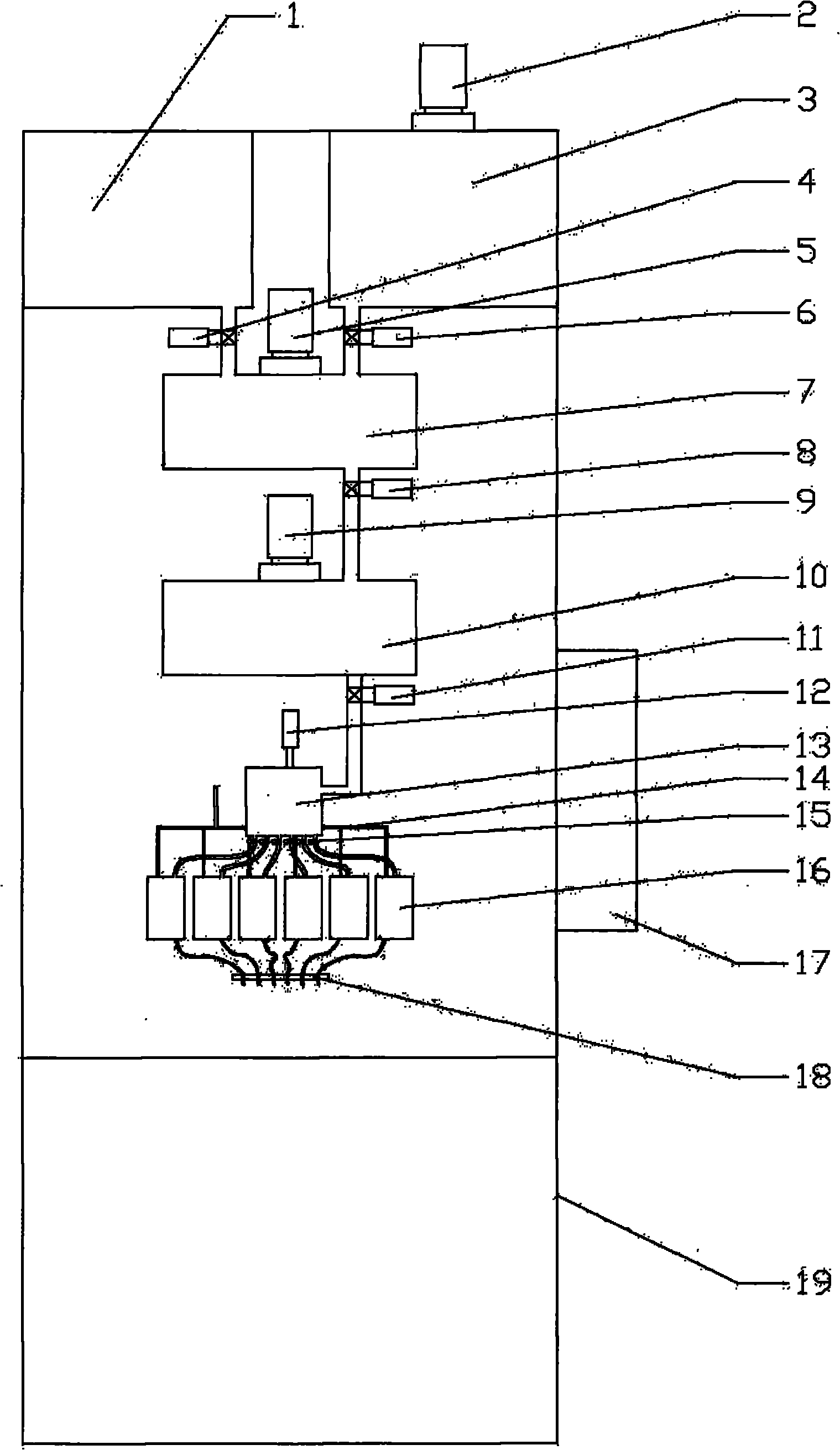
[0019] like figure 1 As shown, the battery glue filling machine includes a frame 19, and the frame 19 is provided with a glue dispensing system, a shearing system, a vacuum system and a controller system 17, and the glue dispensing system, the shearing system, and the vacuum The systems are all connected to the controller system 17, and the glue dispensing system, shearing system, and vacuum pumping system are connected in sequence. The glue distribution system includes acid storage tank 1, water glue shear machine 2, glue storage tank 3, sulfuric acid flow pump 4, glue distribution shear machine 5, water glue flow pump 6, glue distribution bucket 7, temperature control valve 8, storage Glue shearing machine 9 and glue storage bucket 10; Shearing system comprises liquid level valve 11, shearing machine 12 and shearing barrel 13, and vacuum system comprises the vacuum pumping pipe 14 that is connected to vacuum pumping machine, flow valve 15, buffer barrel 16 and glue filling ...

Embodiment 2

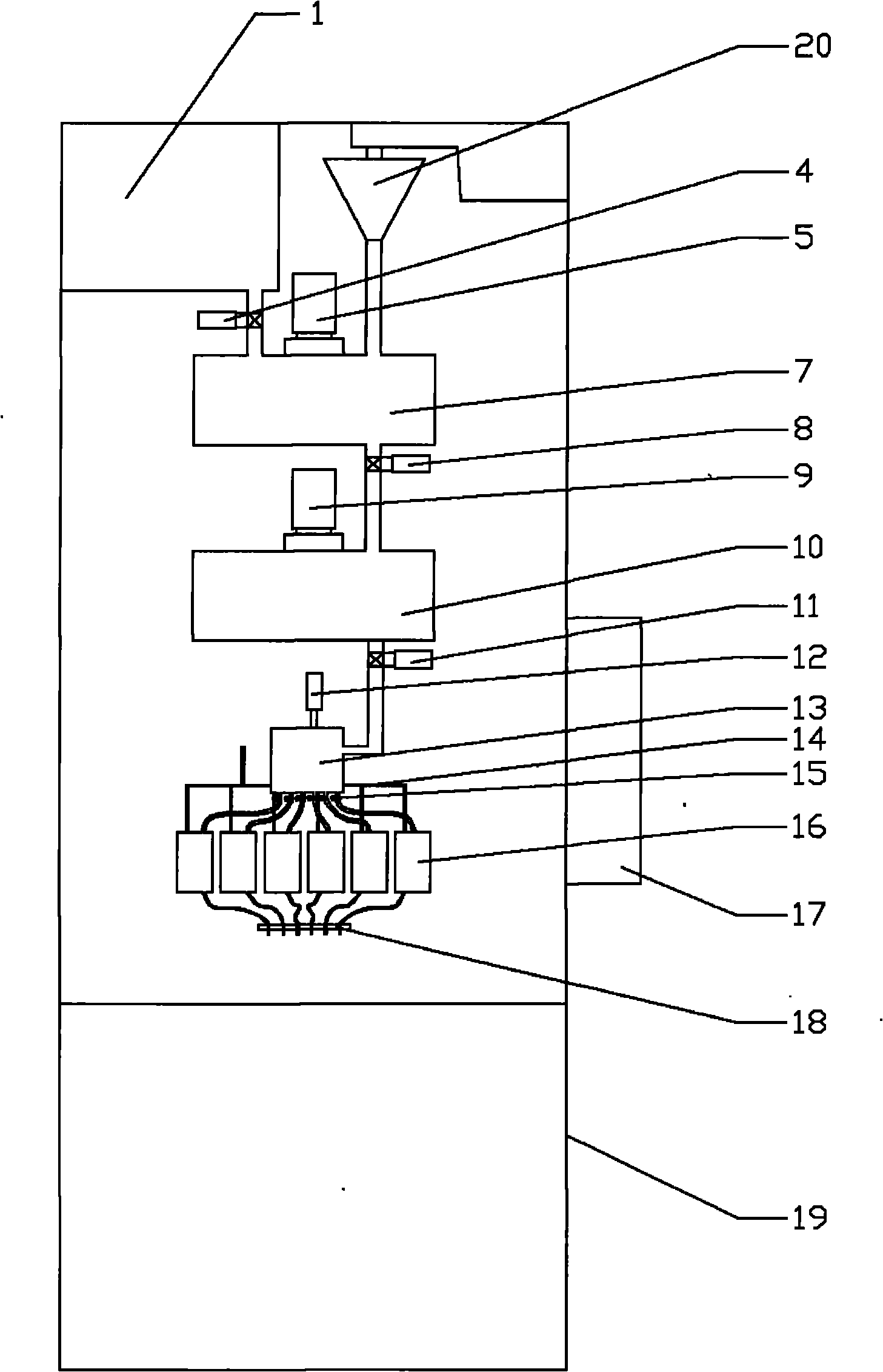
[0032] like figure 2 As shown, the structure of this embodiment is used to directly add silica powder to the glue mixing tank for glue compounding, use silica powder to directly prepare colloidal electrolyte, and replace the water gel scissors in Embodiment 1 by powder weighing machine 20 Cutting machine 2, glue storage tank 3 and water glue flow pump 6, other each parts are all unchanged, to realize same function.

[0033]In this way, in the setting of the controller system 17, the second part is changed to set the amount of sulfuric acid required for the colloidal electrolyte with the sulfuric acid flow pump 4 and the silicon dioxide amount required for the colloidal electrolyte with the powder meter 20 at one time, After the temperature of the acid in the acid storage tank 1 reaches the set process requirements, start the sulfuric acid flow pump 4 and the powder metering machine 20, start the glue dispensing shearer 5, prepare the concentration of each component of the col...


PUM


Abstract

The invention discloses a storage battery glue-pouring machine, comprising a rack on which a glue preparation system, a clipping system, a pumped vacuum system and a controller system are arranged, wherein the glue preparation system, the clipping system and the pumped vacuum system are integrally controlled by the controller system and are successively connected. By adopting the clipping system to replace a traditional cropper to realize even dispersion of electrolytes, and the glue preparation system, the clipping system and the pumped vacuum system are integrally controlled by the same controller system to realize synchronous and successive operation of glue preparation, clipping and pouring, thus ensuring pouring consistency of colloidal electrolytes of colloidal batteries and improving quality of the colloidal batteries, thereby enhancing the storage battery performance. At the same time, the surfaces of a groove, a barrel and a pipe unit are made of a hydrophobic material, thus preventing the colloidal electrolytes from being hung on walls. The pumped vacuum system is controlled by the controller system to realize high-speed and even glue pouring.

Description

【Technical field】 [0001] The invention relates to the perfusion of battery electrolyte, in particular to a glue filling machine for colloidal electrolyte perfusion. 【Background technique】 [0002] At present, in the colloidal electrolyte perfusion process of the battery, the electrolyte needs to go through a series of procedures before it can enter the battery tank after being sheared. During this period, the electrolyte has a gel process for a long time, and the gel time is inconsistent, and the consistency of the battery is difficult to control. As the room temperature changes, it is difficult to control the temperature of the colloidal electrolyte, and the gel time under various conditions cannot be precisely controlled. The colloidal electrolyte is easy to hang on the wall in the glue filling system and block the pipeline, so that the glue adding process cannot be smooth and consistent. 【Content of invention】 [0003] The purpose of the present invention is to solve t...

Claims


Application Information

Patent Timeline
IPC IPC(8): H01M2/36H01M50/627
CPCY02E60/10
Inventor 沈浩宇郑欧刘孝伟陈体衔
Owner CHAOWEI POWER CO LTD
Why Eureka
Try Eureka