Scroll compressor

A scroll compressor and scroll technology, applied in the field of scroll compressors, can solve problems such as leakage, reduced compression capacity, and inability to exert oil sealing effects

Active Publication Date: 2013-02-13
PANASONIC CORP
View PDF1 Cites 0 Cited by
  • Summary
  • Abstract
  • Description
  • Claims
  • Application Information

AI Technical Summary

Problems solved by technology

Therefore, although the oil can be supplied near the compression chamber in the middle of the compression process when the compression has progressed to a certain degree, the process part where the compression chamber seals the low-pressure gas sucked from the suction chamber and the process part just after the compression starts That is, the vicinity of the compression chamber of the outer ring that communicates with the suction chamber is not supplied with oil
In this way, the oil sealing effect cannot be exerted near the compression chamber on the outer ring side that communicates with the suction chamber, and leakage from the compression chamber to the suction chamber side will occur during the process of sealing low-pressure gas, and the compression capacity will be reduced; Leakage occurs between the compression chambers during the start of compression, requiring an increase in input power, etc.
Any of the above situations lead to poor performance
[0006] In particular, when a high-pressure fluid such as carbon dioxide is used as the working fluid, the pressure becomes very high immediately after the compression. Therefore, if the above-mentioned existing structure is adopted, the loss caused by leakage, backflow, etc. is particularly large, and there is no performance Greatly reduces the problem

Method used


Image

  • Scroll compressor
  • Scroll compressor
  • Scroll compressor

Examples


Embodiment 1

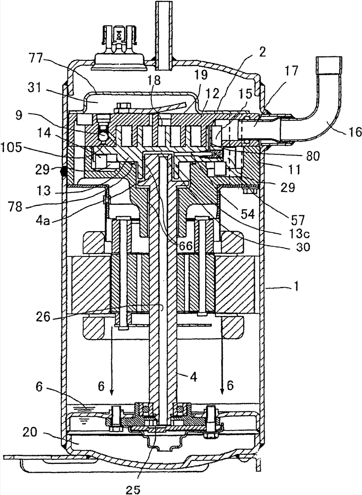
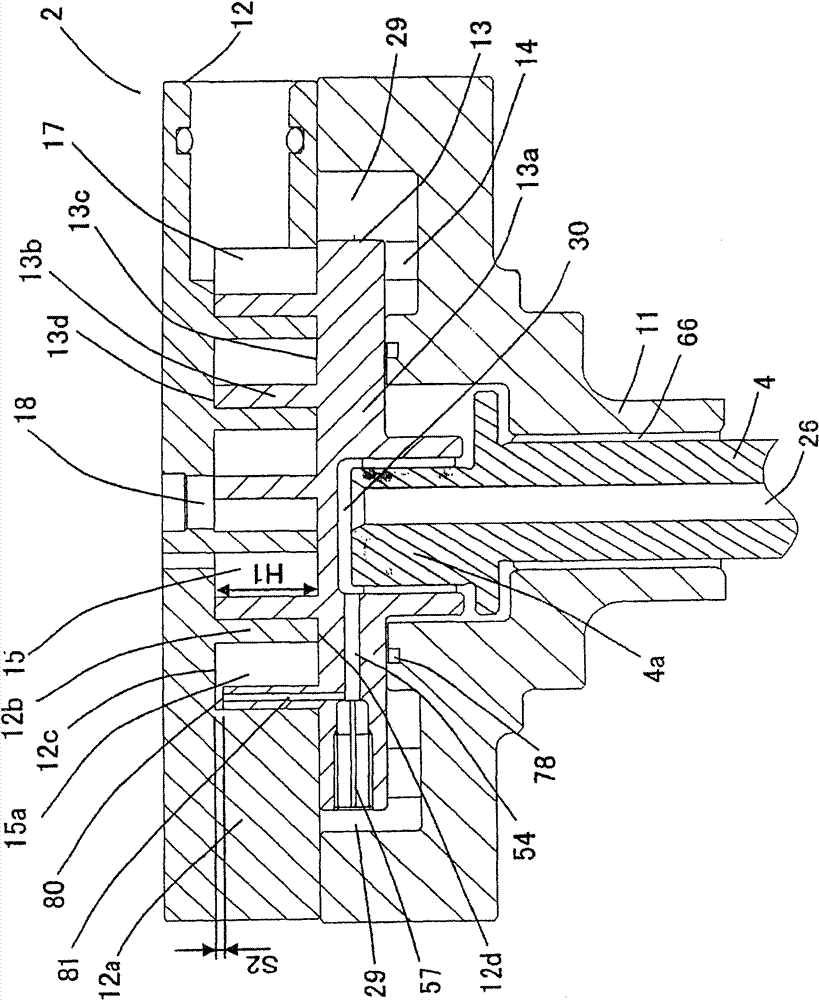
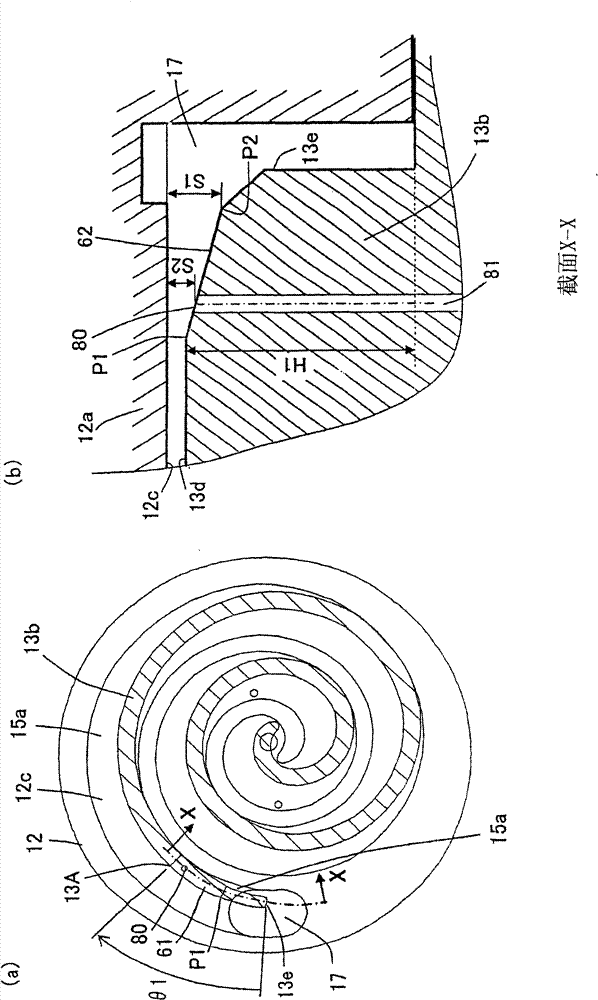
[0030] figure 1 It is a longitudinal sectional view of the scroll compressor in Embodiment 1 of the present invention. figure 2 It is a longitudinal sectional view of the compression mechanism part in this scroll compressor. image 3 (a) is a cross-sectional view of this compression mechanism portion, image 3 (b) for image 3 Cross-sectional view of part X-X in (a). and, in figure 2 In the sectional view of , the right half shows the cross section connecting the discharge port 18 and the suction chamber 17 , and the left half shows the cross section connecting the discharge port 18 and the oil supply hole 80 . The operation and action of the scroll compressors shown in these drawings will be described below.

[0031] Scroll compressor of the present invention such as figure 1 and figure 2 As shown, the main bearing part 11 of the crankshaft 4 is fixed in the airtight container 1 by welding or inserting after heating, and the orbiting scroll 13 engaged with the fix...

Embodiment 2

[0044] Figure 4 It is a longitudinal sectional view of the compression mechanism of the scroll compressor in Embodiment 2 of the present invention, Figure 5 (a) is a cross-sectional view of the compression mechanism of the scroll compressor in Embodiment 2 of the present invention, Figure 5 (b) for Figure 4 Cross-sectional view of part Y-Y of (a). exist Figure 4In the drawing, the right half shows the cross section connecting the discharge port 18 and the suction chamber 17 , and the left half shows the cross section connecting the discharge port 18 and the oil supply hole 80 .

[0045] exist Figure 4 and Figure 5 , the gap S3 in the thrust direction between the scroll tooth upper surface 13d of the orbiting scroll 13 and the scroll tooth groove bottom surface 12c of the fixed scroll 12 gradually increases from the inner ring side to the outer ring side along the circumferential direction. ; In the range from the point P3 on the inner ring side of the scroll tooth...

Embodiment 3

[0051] Image 6 It is a longitudinal sectional view of the orbiting scroll of the scroll compressor in Example 3 of the present invention. The diameter R of the oil supply hole is 20% or more of the wrap thickness t of the orbiting scroll 13 and is 70% or less of the thickness t.

[0052] By setting the diameter R of the oil supply hole 80 to be 20% or more of the thickness t of the wrap tooth of the orbiting scroll 13, it is possible to improve the oil pressure in the vicinity of the compression chamber 15a of the sealing process by sucking low-pressure gas from the suction chamber 17. An oil supply hole 80 passes through the sealing part of the scroll tooth upper surface 13d and the oil supply hole 80 in the thickness direction of the scroll tooth, and provides a uniform and appropriate amount of oil to the compression chamber 15 from the beginning of compression, improving the sealing performance and realizing a high-efficiency High reliability scroll compressor.

[0053]...


PUM


Abstract

The invention provides an effective scroll compressor with high reliability which solves the leakage of a compression chamber from the compression chamber to a suction chamber in a compressing process and from the starting of the compression to the ending, and does not cause a low performance. The scroll compressor comprises an inclined plane with reduced height of scroll teeth of a rotary scroll plate of which a clearance on a thrust direction gradually increases from an inner circle to an outer circle between the upper surface of the scroll teeth of the rotary scroll plate and a groove bottom surface of the scroll teeth of a fixed scroll plate, and in a range of maximum 180 DEG from the outer circle ending part on the upper surface of the scroll teeth of the rotary scroll plate, and an oil supplying hole formed with an opening on the inclined plane. The clearance between the oil supplying hole and the groove bottom surface of the scroll teeth of the fixed scroll plate is easily adjusted because of the inclination of the upper surface of the scroll teeth so as to supply the oil supplied by the oil supplying hole according to the needed minimum amount. The oil is evenly supplied by the oil supplying hole at the beginning of the compression, thereby improving the sealing performance.

Description

technical field [0001] The present invention relates to a scroll compressor used in air conditioners, heat pump water heaters and the like. Background technique [0002] In the scroll compressor, the spiral scroll teeth are erected from the mirror plate to form a fixed scroll and an orbiting scroll, and the fixed scroll and the orbiting scroll mesh with each other, and the orbiting scroll is sandwiched between A compression mechanism is formed between the fixed scroll and the main bearing, and the orbiting scroll moves along a circular orbit driven by a driving mechanism such as a motor. With such a structure, the compression chambers that are alternately formed between the fixed scroll and the orbiting scroll, on both sides of the orbiting scroll inner ring side and the outer ring side of the orbiting scroll, move from the outer ring to the center. During the process, it gradually becomes smaller, and the low-pressure gas is sucked in from the suction chamber on the outer ...

Claims


Application Information

Patent Timeline
Patent Type & Authority Patents(China)
IPC IPC(8): F04C18/02F04C29/00
Inventor 二上义幸森本敬吉田裕文池田明鶸田晃
Owner PANASONIC CORP
Why Eureka
Try Eureka