V-shaped micro-strip meander-line slow wave structure

A technology of slow wave structure and zigzagging lines, applied in the field of traveling wave tube amplifiers, can solve the problems of narrow operating frequency band of traveling wave tubes, limited application development, and small coupling impedance

Inactive Publication Date: 2010-11-24
UNIV OF ELECTRONICS SCI & TECH OF CHINA
View PDF4 Cites 21 Cited by
  • Summary
  • Abstract
  • Description
  • Claims
  • Application Information

AI Technical Summary

Problems solved by technology

[0005] However, the working frequency band of the right-angle microstrip zigzag slow-wave structure traveling wave tube is relatively narrow, and the coupling impedance is relatively small, which limits its application development.

Method used


Image

  • V-shaped micro-strip meander-line slow wave structure
  • V-shaped micro-strip meander-line slow wave structure
  • V-shaped micro-strip meander-line slow wave structure

Examples


Embodiment approach 1

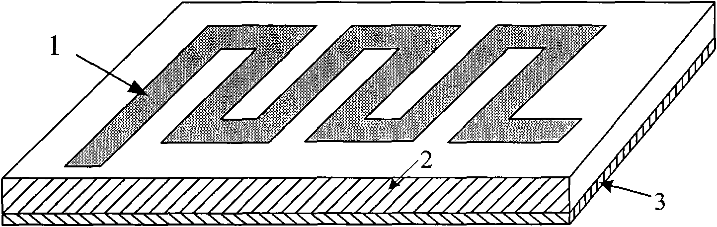
[0027] A V-shaped microstrip meander slow-wave structure, such as image 3 As shown, it includes a microstrip transmission line structure formed by a metal base plate 3 , a dielectric layer 2 and a planar metal line 1 . The dielectric layer 2 is located between the metal bottom plate 3 and the plane metal wire 1 , and its shape is the same as that of the metal bottom plate 3 . The planar metal wire 1 is composed of a plurality of planar metal wire segments of the same shape and size connected end to end to form a zigzag structure; wherein two adjacent planar metal wire segments form a "V" shape or an inverted "V" shape, and a "V" shape or an inverted "V" "The included angle (2θ) of the font is less than 180 degrees.

Embodiment approach 2

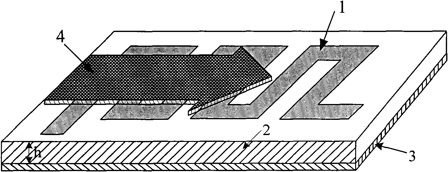
[0029] A V-shaped microstrip meander slow-wave structure, such as Figure 4 As shown, it includes a microstrip transmission line structure formed by a metal base plate 3 , a dielectric layer 2 and a planar metal line 1 . The dielectric layer 2 is located between the metal base plate 3 and the planar metal line 1 , and its shape is the same as that of the planar metal line 1 . The planar metal wire 1 is composed of a plurality of planar metal wire segments of the same shape and size connected end to end to form a zigzag structure; wherein two adjacent planar metal wire segments form a "V" shape or an inverted "V" shape, and a "V" shape or an inverted "V" "The included angle (2θ) of the font is less than 180 degrees.

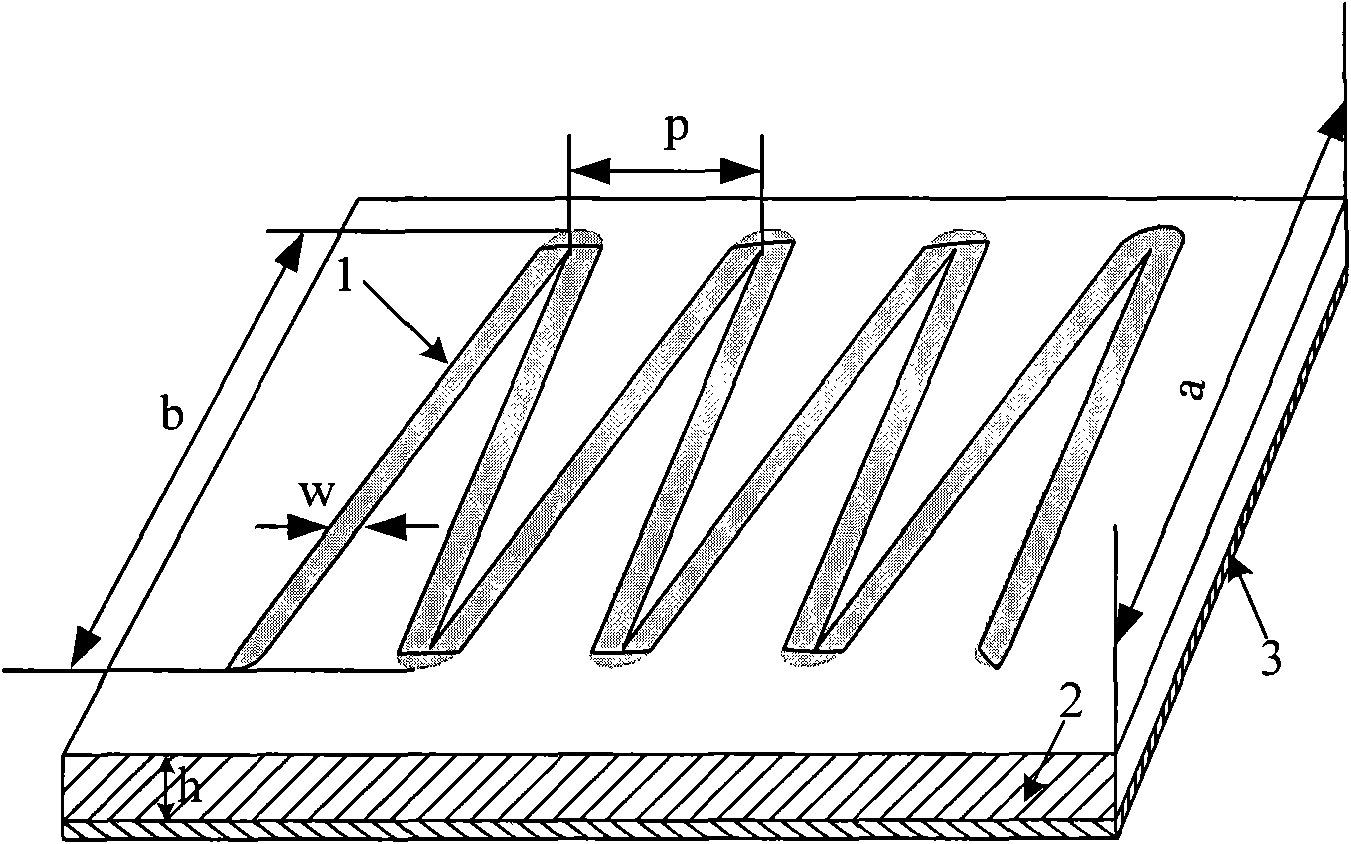
[0030] After confirming that two adjacent sections of planar metal line segments form a "V" shape or an inverted "V" shape with equal angles (periodic structure), determine the relevant dimensions (unit: mm) of the above two implementations: a=0.72, b =0.36, p=0...


PUM


Abstract

The invention discloses a V-shaped micro-strip meander-line slow wave structure, belongs to the technical field of microwave vacuum electronics, and relates to a traveling wave tube amplifier. The V-shaped micro-strip meander-line slow wave structure comprises a micro-strip transmission line structure consisting of a metal bottom plate (3), a dielectric layer (2) and a planar metal wire (1) and is characterized in that: the dielectric layer (2) is positioned between the metal bottom plate (3) and the planar metal wire (1); the planar metal wire (1) has a zigzag structure formed by connecting a plurality of sections of planar metal wires which have the same shape and dimension end to end; and the adjacent two sections of planar metal wires constitute a V shape or a reverse V shape, and the included angle 2theta of the V shape or reverse V shape is less than 180 degrees. The shape of the dielectric layer (2) can be the same as that of the metal bottom plate (3) or the planar metal wire (1). Compared with the conventional right-angle micro-strip meander-line slow wave structure, the V-shaped micro-strip meander-line slow wave structure has wider working band and higher coupling impedance and can further meet the requirements of an equipment system on the device in aspects of working bandwidth, output power, weight and volume.

Description

technical field [0001] The invention belongs to the technical field of microwave vacuum electronics, and relates to a traveling wave tube amplifier. Background technique [0002] Traveling wave tube is the most important type of microwave and millimeter wave source in the field of vacuum electronics. It has the characteristics of high power, high efficiency, high gain, broadband and long life. It is widely used in millimeter wave radar, guidance, communication, microwave remote sensing , radiation measurement and other fields, its performance directly determines the level of equipment. [0003] With the rapid development of modern electronic technology, my country's aerospace engineering and new generation satellites urgently need a large number of millimeter wave sources with broadband, high efficiency, light weight and small size. However, compared with solid-state devices, although the current traveling wave tubes have high power and wide bandwidth, they are bulky and he...

Claims


Application Information

Patent Timeline
Patent Type & Authority Applications(China)
IPC IPC(8): H01J23/24
Inventor 魏彦玉沈飞宫玉彬殷海荣段兆云王文祥
Owner UNIV OF ELECTRONICS SCI & TECH OF CHINA
Why Eureka
Try Eureka