Microstrip band-reject filter with C-shaped annular conduction band defect structure

A band-stop filter and defect structure technology, applied in waveguide devices, electrical components, circuits, etc., can solve the problems of large size and unfavorable filter miniaturization, and achieve large stop-band attenuation, compact structure, and stop-bandwidth Effect

Inactive Publication Date: 2010-11-24
SHANGHAI MARITIME UNIVERSITY
View PDF0 Cites 10 Cited by
  • Summary
  • Abstract
  • Description
  • Claims
  • Application Information

AI Technical Summary

Problems solved by technology

Its purpose is to solve the problem that the traditional microstrip bandstop filter is relatively large in size, which is not conducive to the miniaturization of the filter, and DGS solves this problem. A single unit (such as figure 2 As shown), the band stop characteristic can be realized, but there is a packaging problem in DGS, and DMS solves this problem very well

Method used


Image

  • Microstrip band-reject filter with C-shaped annular conduction band defect structure
  • Microstrip band-reject filter with C-shaped annular conduction band defect structure
  • Microstrip band-reject filter with C-shaped annular conduction band defect structure

Examples


Embodiment Construction

[0016] In order to make it easy to understand the technical means, creative features, objectives and effects achieved by the present invention, the present invention will be further explained below in conjunction with specific drawings.

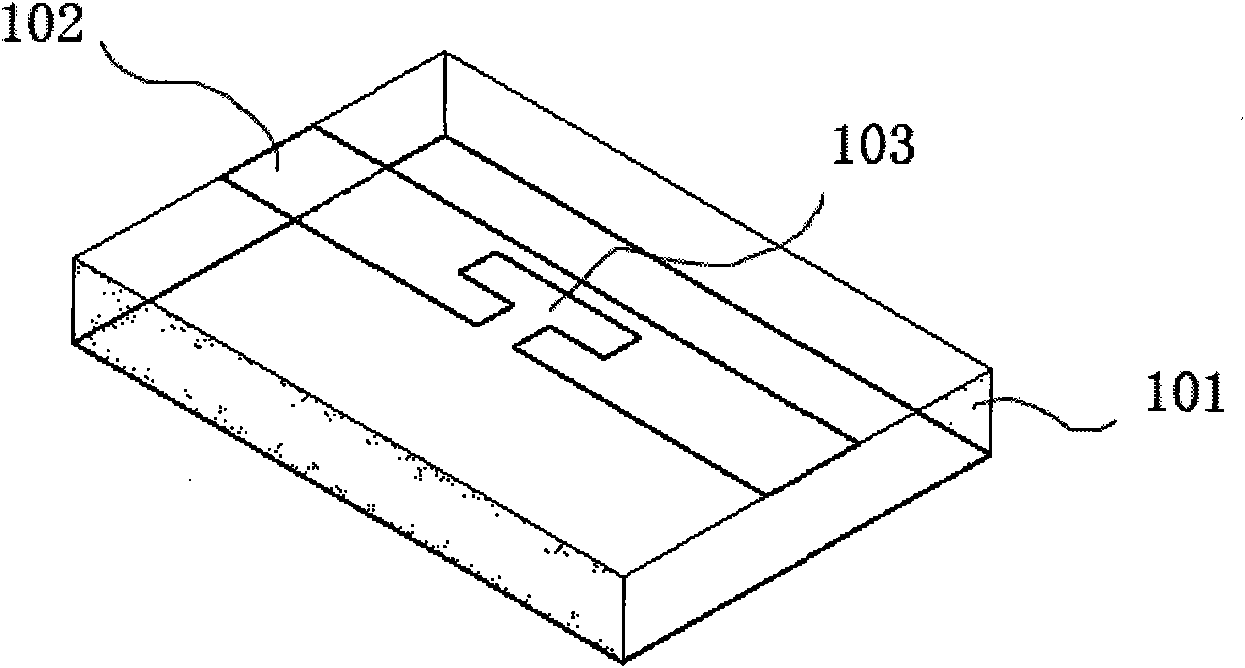
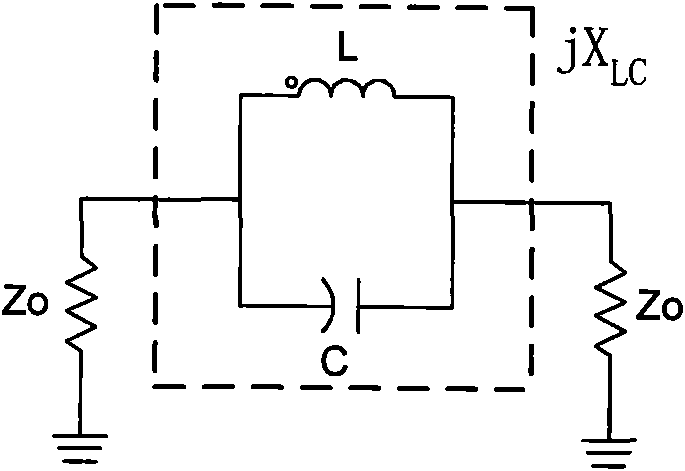
[0017] Such as figure 1 with figure 2 As shown, the microstrip defect structure (DMS), like the defect ground structure (DGS), has similar band rejection characteristics, and its equivalent circuit is an LC parallel resonance circuit (see image 3 ). The DMS unit structure is formed by etching the corresponding structure on the microstrip line conduction band.

[0018] Such as figure 1 As shown, the band stop filter (DMS) with a microstrip defect structure is a ground plate made of copper foil underneath, a dielectric plate 101 in the middle, and a conduction strip 102 made of copper foil on the top. The usual microstrip defect structure (DMS) ) Is to etch the conduction band 102 into a T-shaped or L-shaped groove 103.

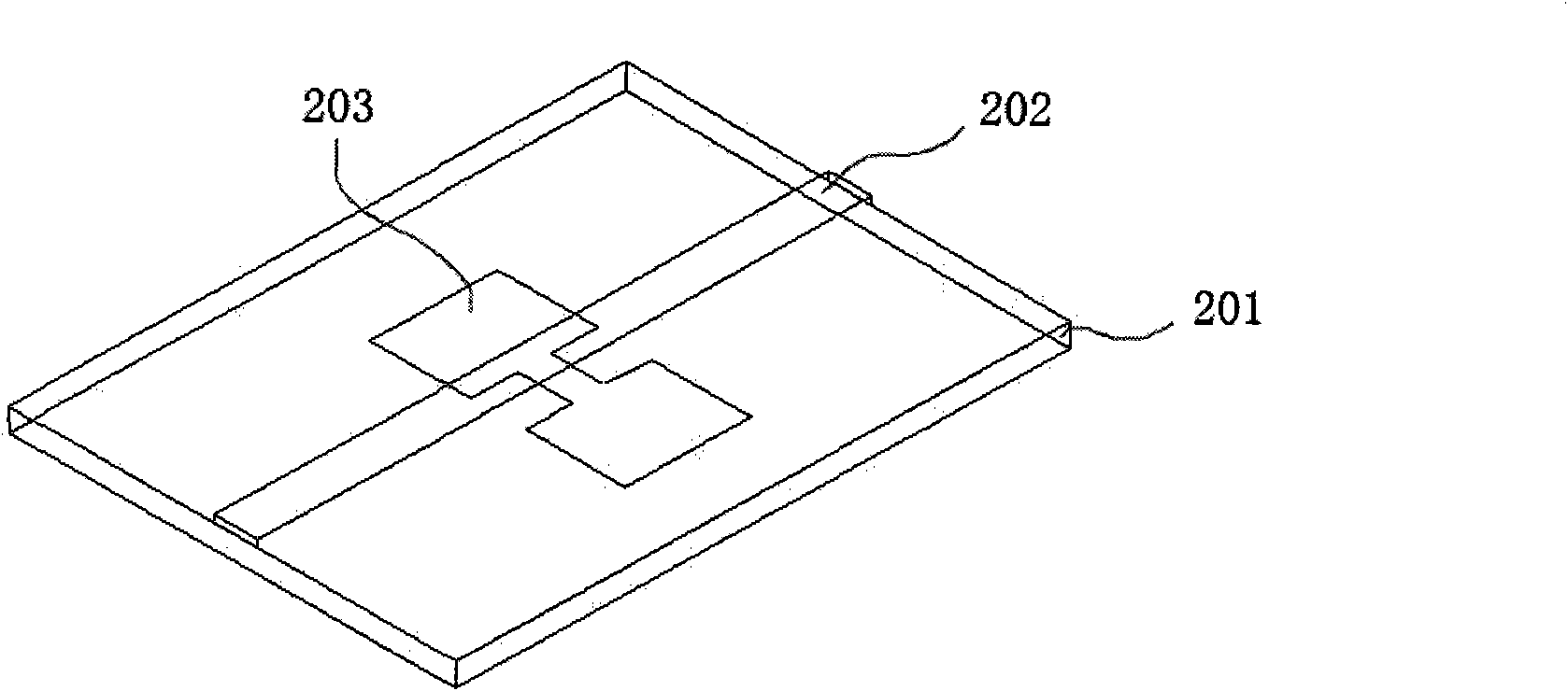
[0019] Such as figure 2 A...


PUM


Abstract

The invention discloses a novel microstrip band-reject filter with a C-shaped annular conduction band defect structure, which comprises a dielectric-slab of which the dielectric constant epsilon r is 2.65 and a ground plate which is arranged on the bottom surface of the dielectric-slab and is made of copper foils. The microstrip band-reject filter is characterized in that a copper conduction band arranged on the bottom surface of the dielectric-slab has two narrower ends and a wider middle part (belonging to a compensated microstrip line); and the middle part of the conduction band is etched with more than one C-shaped annular conduction band defect. The microstrip band-reject filter has the advantages of compact structure, convenient integration, high stopband attenuation, small passband ripple and wide stopband.

Description

Technical field: [0001] The present invention relates to microwave communication, in particular to a novel C-shaped ring conduction band defect structure microstrip band rejection filter. Background technique: [0002] From the perspective of the development of telecommunications, filters have always played an important role in microwave circuits, using more passive components and making continuous progress with the development of communication technology. From a practical point of view, miniaturization is an important research topic for all handheld electronic devices, such as portable mobile phones. In the radio frequency part, although the emergence of monolithic microwave integrated circuits (MMIC) indicates that the miniaturization of radio frequency active circuits such as amplifiers, modulators, and frequency converters is becoming more and more possible. However, there are still many problems to be solved in the optimization of the size reduction of circuits containing r...

Claims


Application Information

Patent Timeline
Patent Type & Authority Applications(China)
IPC IPC(8): H01P1/203
Inventor 张友俊
Owner SHANGHAI MARITIME UNIVERSITY
Why Eureka
Try Eureka