Refrigeration device

A refrigeration device and refrigerant technology, used in refrigerators, refrigeration components, refrigeration and liquefaction, etc., can solve the problems of difficult liquid-phase refrigerants, equal distribution, and large volume of gas-phase refrigerants, and achieve improved cooling performance and low cost. Effect

Inactive Publication Date: 2010-11-24
MITSUBISHI HEAVY IND LTD
View PDF2 Cites 14 Cited by
  • Summary
  • Abstract
  • Description
  • Claims
  • Application Information

AI Technical Summary

Problems solved by technology

However, the volume occupied by the gas-phase refrigerant is relatively large. As mentioned above, it is difficult to equally distribute the liquid-phase refrigerant to multiple refrigerant flow paths, which is the root cause of the above problems.

Method used


Image

  • Refrigeration device
  • Refrigeration device
  • Refrigeration device

Examples


no. 1 example

[0051] Below, use Figure 1 to Figure 3 A first embodiment of the present invention will be described.

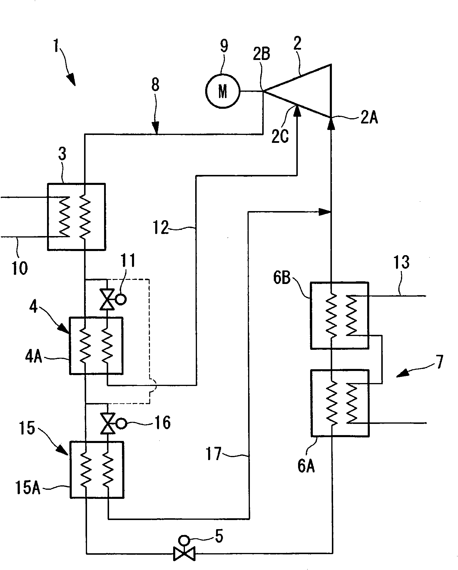
[0052] figure 1 It shows the refrigerating cycle diagram of the turbo refrigerating device according to the first embodiment of the present invention. The turbo refrigeration device 1 has a refrigeration cycle 8 that is connected in sequence by the following components to form a closed circuit. The refrigeration cycle 8 includes: a secondary turbo compressor 2, a condenser 3, an economizer 4, a main expansion valve 5, and two plate heat exchangers. The evaporator 7 constituted by multi-stage connection of the exchangers 6A and 6B in series.

[0053] The two-stage turbo compressor 2 is a multi-stage compressor driven by an inverter motor 9, and has an intermediate suction port 2C provided between a first impeller and a second impeller (not shown in the drawing) in addition to the suction port 2A and the discharge port 2B. , the low-pressure refrigerant gas sucked from the...

no. 2 example

[0072] Use below Figure 4 A second embodiment of the present invention will be described.

[0073] Compared with the above-mentioned first embodiment, this embodiment is different in the structure of the refrigerant pre-cooler 25 . The description of the other points is omitted since they are the same as those of the first embodiment.

[0074] In this embodiment, the refrigerant precooler 25 is constituted by a gas-liquid separator 25A provided on the inlet side of the evaporator 7 (plate heat exchanger 6A). The gas-phase refrigerant separated by the gas-liquid separator 25A returns to the refrigerant suction circuit between the evaporator 7 and the two-stage turbo compressor 2 through the gas circuit 26 having the on-off valve 27 ,

[0075] As described above, even if the refrigerant precooler 25 composed of the gas-liquid separator 25A is provided on the inlet side of the evaporator 7 (plate heat exchanger 6A), it is possible to supply the dryness to the evaporator 7 (pla...

no. 3 example

[0078] Use below Figure 5 A second embodiment of the present invention will be described.

[0079] Compared with the above-mentioned first embodiment, this embodiment is different in the structure of the refrigerant pre-coolers 35 and 36 . The description of the other points is omitted since they are the same as those of the first embodiment.

[0080] Compared with the evaporator 7 composed of a plurality of plate heat exchangers 6A and 6B connected in series and in multiple stages, in this embodiment, the inlets of the plate heat exchangers 6A and 6B are arranged in series and in multiple stages, and are respectively composed of gas-liquid separators 35A and 36A. Refrigerant precoolers 35, 36. The gas-phase refrigerant separated by the respective gas-liquid separators 35A, 36A returns to the refrigerant suction circuit between the evaporator 7 and the two-stage turbo compressor 2 via the gas circuits 37 , 39 having the on-off valves 38 , 40 .

[0081] As described above, ...


PUM


Abstract

A refrigeration device in which a refrigerant supplied to an evaporator is pre-cooled and supplied as a single phase liquid refrigerant with the degree of dryness of the refrigerant substantially zero. This increases the amount of heat exchange in the evaporator, enhancing cooling performance and enabling downsizing of the evaporator. The refrigeration device (1) has a refrigeration cycle (8) formed by sequentially connecting a compressor (2), a condenser (3), an economizer (4), an expansion valve (5), and the evaporator (7). The compressor (2) compresses the refrigerant. The condenser (3) condenses high-pressure gas refrigerant. The economizer (4) evaporates a part of the condensed liquid refrigerant and cools the liquid refrigerant by latent heat of the evaporation, and has a circuit for inletting the evaporated intermediate-pressure refrigerant into an intermediate inlet opening of the compressor. The expansion valve (5) adiabatically expands the liquid refrigerant. The evaporator (7) evaporates the adiabatically expanded refrigerant. Between the economizer (4) and the evaporator (7) is provided a refrigerant pre-cooler (15) for pre-cooling the refrigerant to be supplied to the evaporator (7).

Description

technical field [0001] The present invention relates to a refrigeration device, and more particularly to a refrigeration device suitable for use in a turbo refrigeration device using a plate heat exchanger in an evaporator. Background technique [0002] Conventionally, a turbo refrigerator is used as a large-capacity heat source device, and a shell-and-tube heat exchanger suitable for large heat exchange is used in its condenser and evaporator. But recently, with the rapid progress of manufacturing technology, it is possible to manufacture a relatively small-capacity turbo refrigeration device of less than 100 refrigerated tons. This small capacity turbo chiller uses a plate heat exchanger in addition to a shell and tube heat exchanger. On the other hand, in order to have high-efficiency performance characteristics, a turbo refrigerator also requires a large-scale and high-performance specification for the plate heat exchanger used. [0003] Plate heat exchangers generally...

Claims


Application Information

Patent Timeline
Patent Type & Authority Applications(China)
IPC IPC(8): F25B1/053F25B1/00F25B1/10
CPCF25B2400/23F25B2400/13F25B1/10F25B13/00F25B9/006F25B1/053
Inventor 上田宪治松仓纪行
Owner MITSUBISHI HEAVY IND LTD
Why Eureka
Try Eureka