Horizontal flange blank hot coiling machine
A flange and blank technology, which is applied in the field of horizontal flange blank hot coiling machines, can solve the problems of increased center of gravity, poor stability, and reduced yield of the whole machine, so as to improve the degree of automation, improve material utilization, and improve efficiency. Loading and unloading with ease
- Summary
- Abstract
- Description
- Claims
- Application Information
AI Technical Summary
Problems solved by technology
Method used
Image
Examples
Embodiment 1
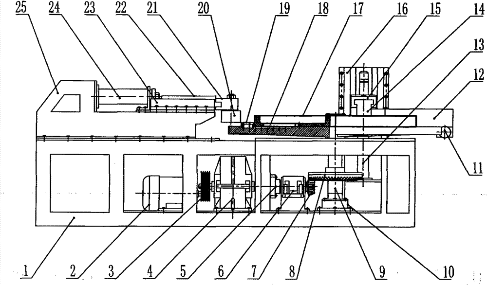
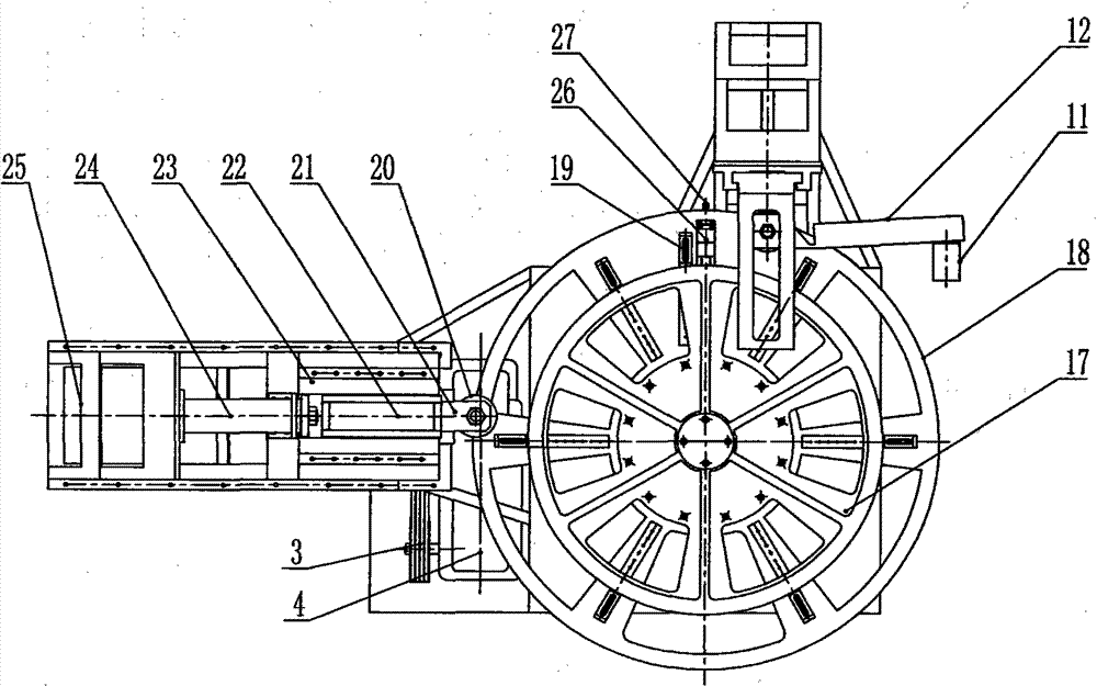
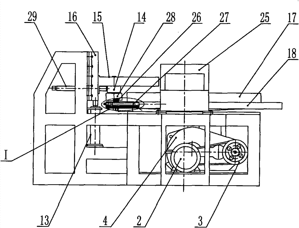
[0028] Embodiment one: see figure 1 , figure 2 , image 3 , Figure 4 , a horizontal flange blank hot coiling machine, including a frame 1, a motor 2, a reducer 3, a transverse bearing seat 6 and a vertical bearing seat 10 are fixedly installed in sequence on the lower side of the frame, and the motor 2 and the reducer 3 input The shaft is connected through the belt and the pulley 3, the output shaft of the reducer is connected with the driving main shaft through the coupling 5, the driving main shaft is installed in the transverse bearing seat 6 and the driving bevel gear 7 (small bevel gear) is installed at the end of the driving main shaft .
[0029] A mold chassis 18 installed horizontally, its center axis 13 is vertically installed in the upper and lower bearing seats of the frame (the lower end is installed in the vertical bearing seat 10 on the lower side of the frame) and installed on the mold chassis center axis 13 There are driven bevel gears 8 large bevel gears...
Embodiment 2
[0037] Embodiment 2: The accompanying drawings are not drawn, and the content is basically the same as Embodiment 1, and the similarities will not be repeated. The difference is that the horizontal drive shaft and the vertical central shaft are driven through a worm gear and a worm.
Embodiment 3
[0038] Embodiment 3: The accompanying drawings are not drawn, and the content is basically the same as that of Embodiment 1, and the similarities will not be repeated. The difference is that: the hydraulic cylinder of the adjustable lifting guide device is equipped with oil inlet and outlet pipes respectively. A solenoid valve, the solenoid valve is connected to the signal output end of the automatic control system to realize the synchronization of the adjustable lifting guide device and the spiral curling progress of the flange blank.
PUM
 Abstract
Description
Claims
Application Information
 - R&D
- Intellectual Property
- Life Sciences
- Materials
- Tech Scout
- Unparalleled Data Quality
- Higher Quality Content
- 60% Fewer Hallucinations
Browse by: Latest US Patents, China's latest patents, Technical Efficacy Thesaurus, Application Domain, Technology Topic, Popular Technical Reports.
© 2025 PatSnap. All rights reserved.Legal|Privacy policy|Modern Slavery Act Transparency Statement|Sitemap|About US| Contact US: help@patsnap.com


