Smoke waste heat utilization system

A flue gas waste heat and flue technology, used in preheating, waste heat treatment, heat storage heaters, etc., can solve the problems of easy fouling and corrosion, increased flue resistance, affecting heat exchange effect, etc., and avoid working fluids. Leakage, low running resistance and small footprint effect

Inactive Publication Date: 2010-12-01
晁岱军
View PDF0 Cites 4 Cited by
  • Summary
  • Abstract
  • Description
  • Claims
  • Application Information

AI Technical Summary

Problems solved by technology

This problem has not been well resolved for a long time
[0003] The temperature of the heat-absorbing section of the heat pipe technology is low, lower than the dew point temperature, and it is easy to accumulate dust and corrode, resulting in an increase in the resistance of the flue;
[0004]

Method used


Image

  • Smoke waste heat utilization system
  • Smoke waste heat utilization system
  • Smoke waste heat utilization system

Examples


Embodiment

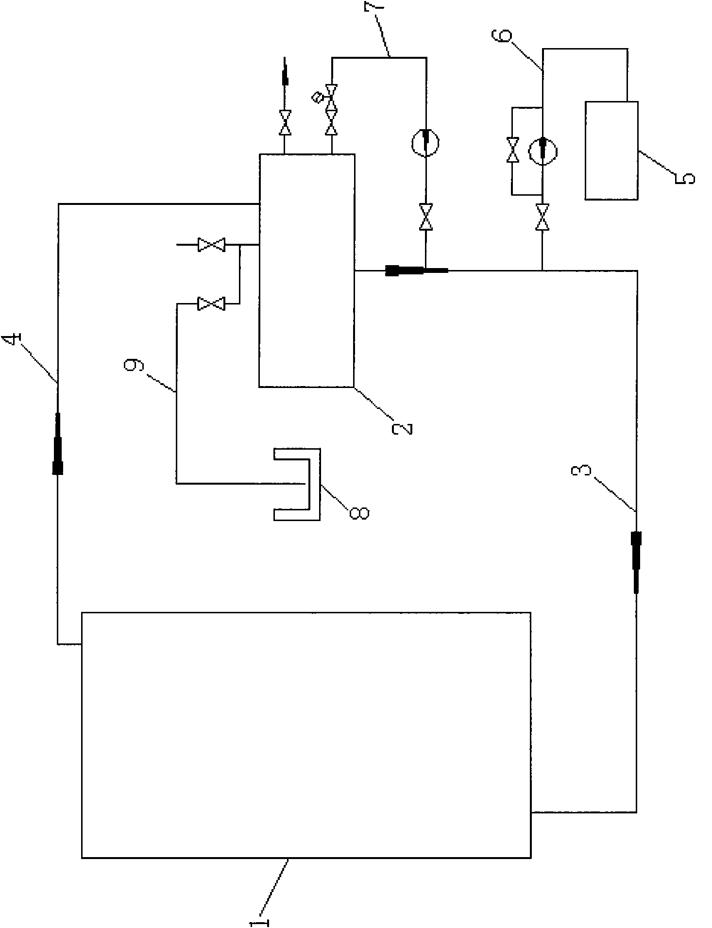
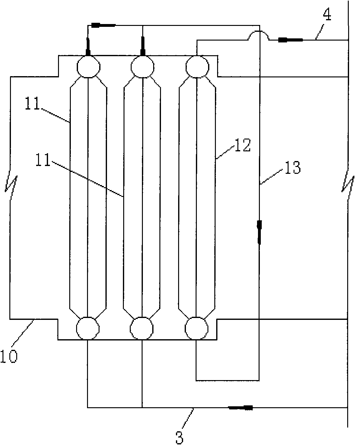
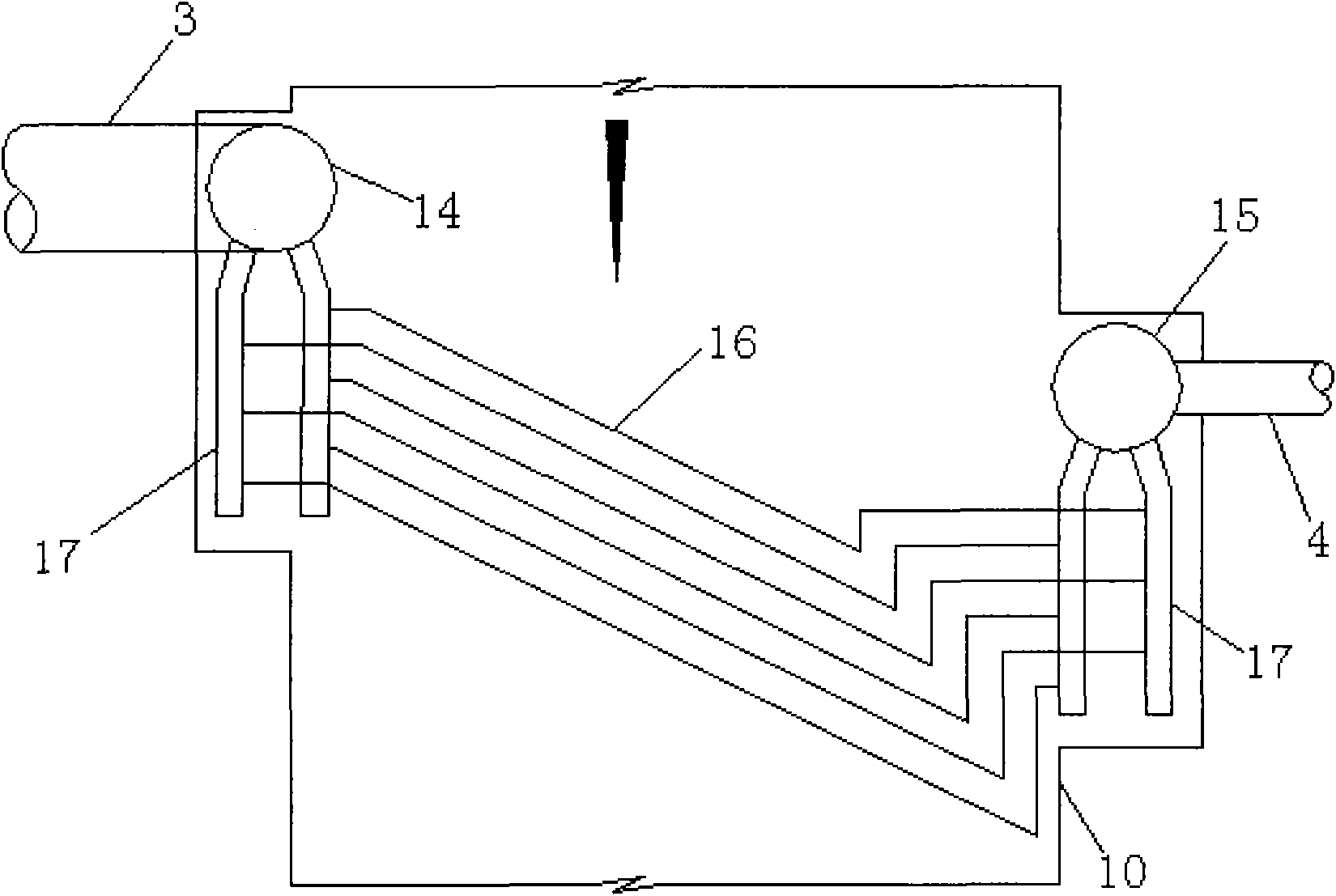
[0023] Embodiment: A flue gas waste heat utilization system, including a heat exchange boiling device 1 installed on a flue 10 and a heat exchange condensing device 2 for heating a heat medium, and the installation height of the heat exchange condensing device is higher than that of the heat exchange The installation height of the boiling device, the condensate outlet of the heat exchange condensing device and the liquid inlet of the heat exchange boiling device are connected with a condensate conduit 3, and the vapor outlet of the heat exchange boiling device is connected with the gas inlet of the heat exchange condensing device. The steam guide pipe 4, the heat transfer medium of the flue gas waste heat utilization system adopts chemical working fluids, which can be ammonia water, alcohol and other chemical working fluids with low boiling point and strong heat storage capacity. Specific chemical working fluids can be selected according to different waste heat parameters. Ther...


PUM


Abstract

The invention discloses a smoke waste heat utilization system. In the smoke waste heat utilization system, a chemical working medium is used as a heat-transfer medium, heat circulation and waste heat utilization efficiency is improved according to the characteristics of low-boiling point and heat absorption of the chemical working medium; meanwhile, the concentration of the chemical working medium is adjustable, so the boiling point of the working medium can be adjusted by adjusting the concentration of the chemical working medium for adapting to different parameters of waste heat. The arrangement range of a heat exchange boiling device of the smoke waste heat utilization system is so wide that the heat exchange boiling device can be arranged on a horizontal flue as well as on a flue which forms an inclined angle of more than 15 DEG C with the ground. The heat exchange boiling device comprises a vertical flue and an elbow.

Description

technical field [0001] The present invention relates to an energy-saving technology for recovering flue gas waste heat, in particular to a waste heat utilization technology that improves the original split heat pipe heat exchanger and uses chemical working fluid as heat transfer medium without power and closed circuit system. Background technique [0002] Condensation on the heating surface of boilers, industrial kilns and chemical heating equipment in low-temperature areas is an important cause of corrosion. To solve the problem of dew condensation on this part of the heating surface, it is necessary to increase the wall temperature to make it above the dew point temperature. This problem has not been well resolved for a long time. The status quo is that the exhaust gas temperature has to be increased, and the temperature of the heated wall surface at the tail is also increased accordingly, so that the condensation problem can be alleviated. But this reduces the filtrati...

Claims


Application Information

Patent Timeline
IPC IPC(8): F24H7/00F24H7/02F22D1/00F27D17/00
CPCY02P10/25
Inventor 晁岱军
Owner 晁岱军
Why Eureka
Try Eureka