Compressed air measuring and controlling system and method for power plant instrument

A compressed air, measurement and control system technology, applied in the direction of electrical program control, comprehensive factory control, comprehensive factory control, etc., can solve the problems of measuring device hazards, limited application range, general anti-interference ability, etc., to achieve reliable operation and ensure safe operation , the effect of prolonging the service life

Active Publication Date: 2010-12-01
ELECTRIC POWER RESEARCH INSTITUTE OF STATE GRID SHANDONG ELECTRIC POWER COMPANY +1
View PDF4 Cites 6 Cited by
  • Summary
  • Abstract
  • Description
  • Claims
  • Application Information

AI Technical Summary

Problems solved by technology

[0011] 1 The traditional humidity detection method cannot meet the detection requirements of ultra-low humidity of compressed air for instrumentation in power plants
[0012] 2 Existing ultra-low air humidity detection methods mainly include capacitive water analyzers, electrolytic water analyzers, piezoelectric quartz crystal moisture meters, etc., and their application scope is limited to the detection of atmospheric pressure gases without oil and dust
[0013] 3 Analysis of trace moisture in gas plays a very important role in production and scientific research. There are many types of moisture analyzers, but generally speaking, affected by many factors, there are still many difficulties in using the moisture meter stably and measuring results accurately.
[0016] 1. What needs to be carried out is the measurement of ultra-low humidity, the measurement progress is very demanding, and the existing measurement methods have general anti-interference ability
[0017] 2. The oil content and dust in the compressed air will affect the measurement accuracy and cause harm to the measurement device
[0021] 6. Measuring devices and pipelines have high requirements for tightness

Method used


Image

  • Compressed air measuring and controlling system and method for power plant instrument
  • Compressed air measuring and controlling system and method for power plant instrument
  • Compressed air measuring and controlling system and method for power plant instrument

Examples


Embodiment Construction

[0051] The present invention will be further described below in conjunction with the accompanying drawings and embodiments.

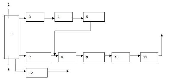
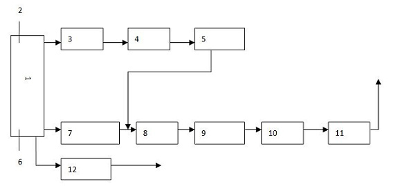
[0052] figure 1 Among them, it includes a gas storage tank 1, the gas storage tank 1 is connected with the measurement circuit, and a purge circuit is also connected between the gas storage tank 1 and the measurement circuit.

[0053] The measuring circuit is provided with a decompression regulating valve 7, a second needle valve 8, a detection device 9, a pressure gauge 10 and a third needle valve 11 at the end in sequence, and the decompression regulating valve 7 is connected to the gas storage tank 1;

[0054]The purge circuit includes a pressure reducing valve 3, a first needle valve 4 and an oil and water filter device 5 connected in sequence, the pressure reducing valve 3 is connected to the gas storage tank 1; the oil and water filter device 5 is connected to the second needle valve 8 connections.

[0055] The gas storage tank 1 is provided wit...


PUM


Abstract

The invention relates to compressed air measuring and controlling system and method for a power plant instrument. The compressed air measuring and controlling system can effectively monitor compressed air so that and the pneumatic equipment in a power plant acts more reliably and timely. The compressed air measuring and controlling system comprises an air storage tank, wherein the air storage tank is connected with a measuring loop, a sweeping loop is connected between the air storage tank and the measuring loop, the measuring loop is provided with a pressure control loop, the tail end of the pressure control loop is connected with a third needle valve, the sweeping loop comprises a reducing valve, a first needle valve and an oil and water filtering device which are sequentially connected, the reducing valve is connected with the air storage tank, the oil and water filtering device is connected with the pressure control loop, and the devices are connected with a decentralized control system.

Description

[0001] technical field [0002] The invention relates to a compressed air measurement and control system for instrumentation in a power plant and a method thereof. Background technique [0003] As one of the power plants, compressed air and electricity are equally important. However, the quality monitoring of the compressed air for instrument use is often neglected, and as a result, the quality of the compressed air for instrument use is degraded, and accidents that endanger the safe operation of the unit due to the refusal of the pneumatic actuator occur from time to time. [0004] In power generation enterprises, the humidity in the compressed air for instrument use is a mandatory inspection item in the thermal supervision ("DL / T774-2004-7.1.2.3.3f article of "Operation Regulations for Maintenance of Thermal Automation System in Thermal Power Plants"), it is the guarantee system Indicators that must be controlled for safety and stability (GB / T13277-91 "General Compres...

Claims


Application Information

Patent Timeline
Patent Type & Authority Applications(China)
IPC IPC(8): G05B19/418
CPCY02P90/02
Inventor 李华东
Owner ELECTRIC POWER RESEARCH INSTITUTE OF STATE GRID SHANDONG ELECTRIC POWER COMPANY
Why Eureka
Try Eureka