Multistage coupling heat accumulating type solar heat-power cogeneration system

A technology of combined heat and power and solar energy, which is applied to solar thermal power generation, solar thermal installations, and mechanical power generation with solar energy, etc., can solve the problems of inability to form energy cascade utilization, lack of direct heat transfer coupling, and inability to perform combined heat and power supply, etc. To achieve the effect of facilitating large-scale production and popularization and application, improving use efficiency and simple structure

Inactive Publication Date: 2010-12-08
SUN YAT SEN UNIV +1
View PDF5 Cites 15 Cited by
  • Summary
  • Abstract
  • Description
  • Claims
  • Application Information

AI Technical Summary

Problems solved by technology

The dual-stage regenerative solar thermal power generation system combined with trough and tower (200810102204.0) proposes a device combining trough thermal power generation and tower thermal power generation, and uses a low-temperature thermal storage subsystem and a high-temperature thermal storage subsystem for heat storage and heat transfer. However, there is no direct heat transfer coupling between the two thermal storage subsystems, and cogeneration of heat and power cannot be performed.
Solar low-temperature thermal power generation and combined cooling and heating system (200810024294.6) proposed a combined cooling, heating and power device based on a compound parabolic collector. In addition to the low operating temperature, the thermal power generation, heat storage, heating and cooling subsystems of the system are all It is a parallel structure and cannot form a cascade utilization of energy

Method used


Image

  • Multistage coupling heat accumulating type solar heat-power cogeneration system
  • Multistage coupling heat accumulating type solar heat-power cogeneration system
  • Multistage coupling heat accumulating type solar heat-power cogeneration system

Examples


Embodiment 1

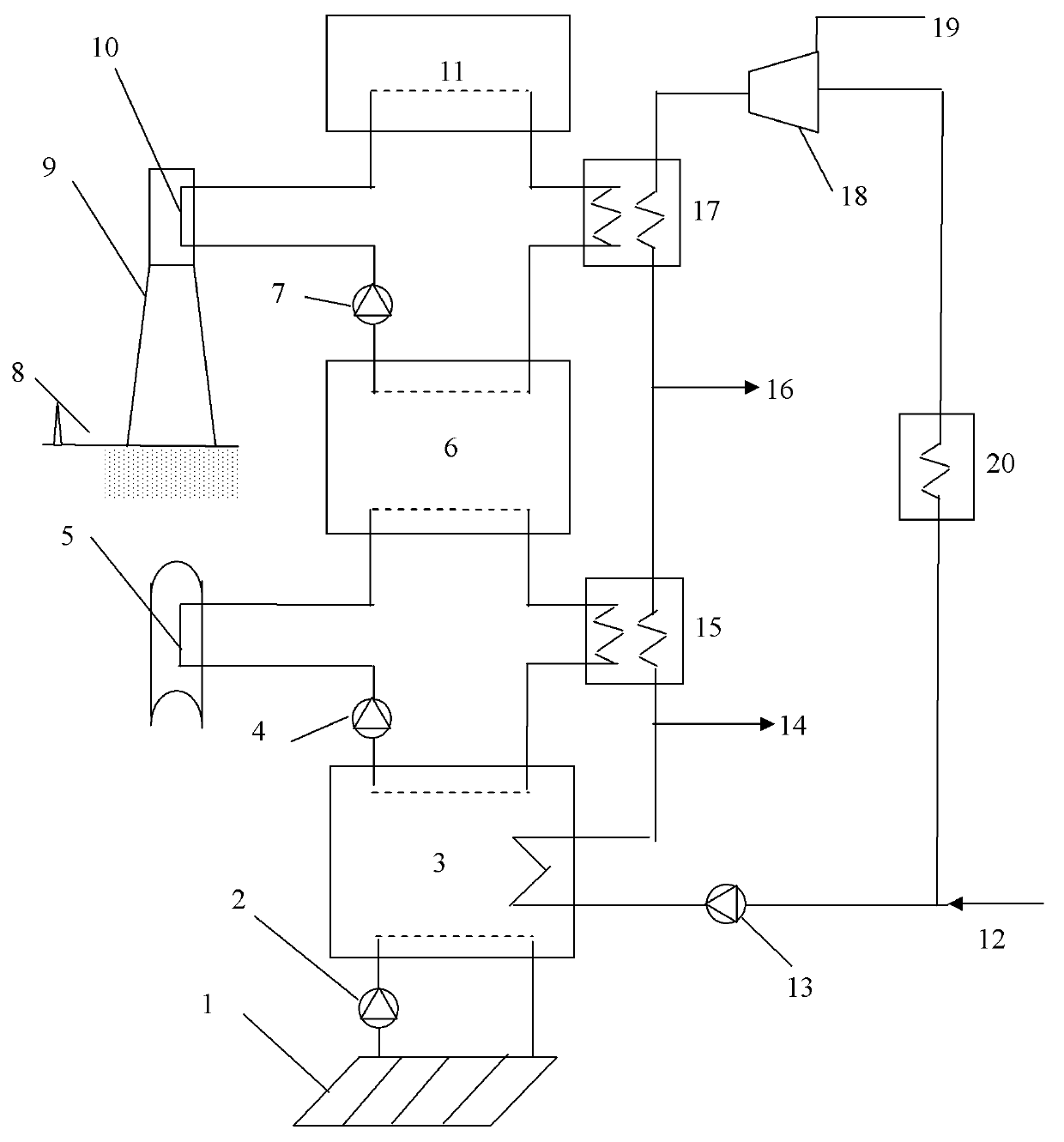
[0029] A multi-stage coupled regenerative solar heat and power cogeneration system, its structure is as follows figure 1 As shown, the tower-type heat absorption heat storage heat transfer subsystem includes a heliostat field 8, a concentrating tower 9, a heat absorber 10, a high temperature resistant pump 7, a high temperature heat accumulator 11 and pipelines. The working temperature of the high-temperature heat transfer and heat storage medium is 300°C-700°C, usually high-temperature mixed molten salt, liquid metal, etc. The trough heat absorption heat storage heat transfer subsystem includes a parabolic trough mirror field and a vacuum tube heat absorber 5, a pump 4, a medium temperature coupled heat accumulator 6 and pipelines. The working temperature of medium temperature heat transfer and heat storage medium is 100°C-400°C, usually high temperature resistant heat transfer oil, etc. The plate heat absorption heat storage heat transfer subsystem includes a plate heat col...


PUM


Abstract

The invention provides a multistage heat accumulating type solar heat-power cogeneration system which comprises a tower type heat absorption-accumulation-transfer subsystem, a tank type heat absorption-accumulation-transfer subsystem, a flat plate type heat absorption-accumulation-transfer subsystem and a heat-power cogeneration subsystem, wherein the tower type heat absorption-accumulation-transfer subsystem, the tank type heat absorption-accumulation-transfer subsystem and the flat plate type heat absorption-accumulation-transfer subsystem are coupled through a moderate temperature coupling heat accumulator and a low temperature coupling heat accumulator; and the heat-power cogeneration system comprises a power supply mode, a heat supply mode and a heat-power cogeneration mode, and operates together with the three heat absorption-accumulation-transfer subsystems. The invention organically combines the solar tower type, tank type and flat plate type heat collecting systems to form high temperature, moderate temperature and low temperature three-stage heat accumulators; and thus, the invention can meet the requirements for industrial large-scale solar moderate temperature and high temperature heat utilization, and is beneficial to the comprehensive cascading utilization of energies.

Description

technical field [0001] The invention relates to the field of solar heat utilization, in particular to a multi-stage coupled heat storage type solar heat and power cogeneration system. Background technique [0002] Energy shortage and environmental problems have become a major bottleneck restricting the development of the global economy and society, and will affect the living conditions of human beings in the future. Solar energy is the most abundant and widely available form of renewable energy in my country and the world, and because of its clean and non-polluting characteristics, it plays a particularly important role in solving energy crisis and environmental problems. Solar thermal utilization is the basic way of solar energy utilization. According to energy grade and working temperature, it is mainly divided into: high-temperature thermal utilization of solar energy, medium-temperature thermal utilization and low-temperature thermal utilization. Solar medium and high t...

Claims


Application Information

Patent Timeline
Patent Type & Authority Applications(China)
IPC IPC(8): F03G6/06F24J2/34F24J2/46
CPCY02E10/46Y02P80/15Y02P80/20
Inventor 陆建峰丁静杨建平杨晓西杨敏林
Owner SUN YAT SEN UNIV
Why Eureka
Try Eureka