Silicon on insulator (SOI) wafer double-mask etching-based vertical comb teeth driven torsional micro-mirror and manufacturing method thereof

A vertical comb-tooth drive, micro-torsion mirror technology, applied in the photoengraving process of the pattern surface, the process for producing decorative surface effects, the micro-structure technology, etc., can solve the problem of large process error, high cost and complex process steps and other problems to achieve the effect of avoiding adhesion between comb teeth and reducing process cost

Inactive Publication Date: 2010-12-08
NORTHWESTERN POLYTECHNICAL UNIV
View PDF4 Cites 45 Cited by
  • Summary
  • Abstract
  • Description
  • Claims
  • Application Information

AI Technical Summary

Problems solved by technology

[0007] In order to overcome the problems of complex process steps, large process errors and high cost in the existing vertical comb-driven micro-torsion

Method used


Image

  • Silicon on insulator (SOI) wafer double-mask etching-based vertical comb teeth driven torsional micro-mirror and manufacturing method thereof
  • Silicon on insulator (SOI) wafer double-mask etching-based vertical comb teeth driven torsional micro-mirror and manufacturing method thereof
  • Silicon on insulator (SOI) wafer double-mask etching-based vertical comb teeth driven torsional micro-mirror and manufacturing method thereof

Examples


Embodiment 1

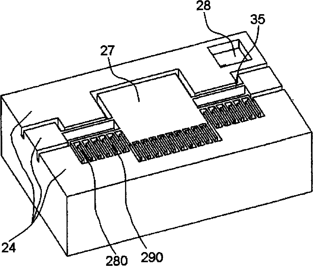
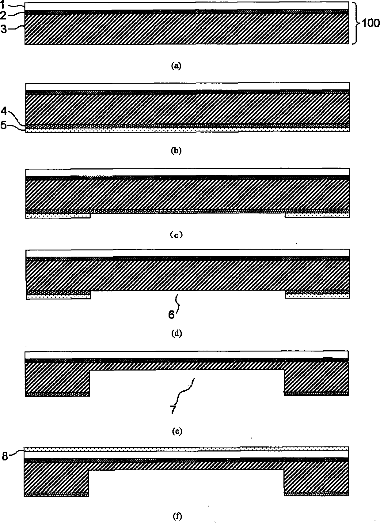
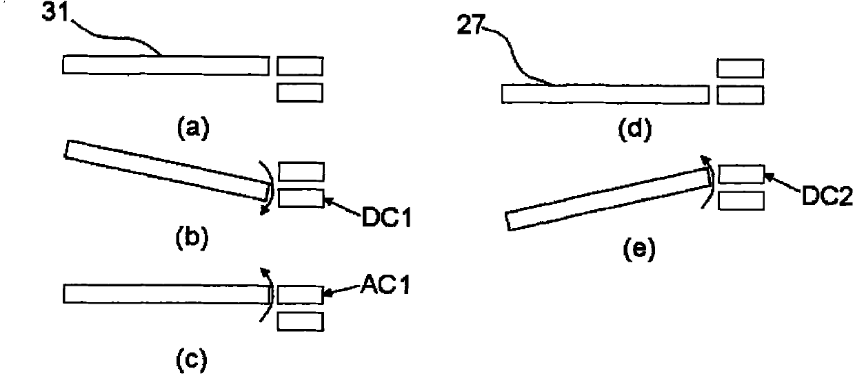
[0046] The vertical comb driven micro-torsion mirror based on SOI wafer double-mask etching in this embodiment sequentially includes a device layer 1, an insulating layer 2, and a base layer 3 with the same structure; the device layer 1 includes movable parts separated from each other and the fixed part, the movable part and the fixed part are separated by the device layer insulation groove 230, and the movable part is composed of the device layer mirror surface 31, the device layer torsion beam 220, the device layer anchor region 14 and the device layer movable comb teeth 210, The device layer mirror 31 is respectively connected to the device layer anchor regions 14 on both sides through the device layer torsion beams 220 at both ends. The movable comb 210; the fixed part is the part arranged separately and arranged around the movable part, including the device layer anchor point 29 without comb teeth, and a corresponding set of device layer fixed anchor points fixed on the de...

Embodiment 2

[0062] The vertical comb driven micro-torsion mirror based on SOI wafer double-mask etching in this embodiment sequentially includes a device layer 1, an insulating layer 2, and a base layer 3 with the same structure; the device layer 1 includes movable parts separated from each other and the fixed part, the movable part and the fixed part are separated by the device layer insulation groove 230, and the movable part is composed of the device layer mirror surface 31, the device layer torsion beam 220, the device layer anchor region 14 and the device layer movable comb teeth 210, The device layer mirror 31 is respectively connected to the device layer anchor regions 14 on both sides through the device layer torsion beams 220 at both ends. The movable comb 210; the fixed part is the part arranged separately and arranged around the movable part, including the device layer anchor point 29 without comb teeth, and a corresponding set of device layer fixed anchor points fixed on the de...


PUM


Abstract

The invention discloses a silicon on insulator (SOI) wafer double-mask etching-based vertical comb teeth driven torsional micro-mirror and a manufacturing method thereof, which belong to the fields of micro-electro-mechanical systems and micromachining. The torsional micro-mirror is driven by single side comb teeth and is provided with three layers of moveable parts and fixed parts with the same structure. The torsional micro-mirror can work in a static mode or in a dynamic mode by applying voltage signals to different comb teeth. The method for manufacturing the vertical comb teeth driven torsional micro-mirror is characterized in that: single SOI wafer processing technology is adopted without multi-layer thin film sedimentation or bonding technology; the whole technological process only needs two mask plates; the upper and lower vertical comb teeth are etched by one mask without an alignment error problem of the comb teeth; and the technological process does not need hydrogen fluoride (HF) corrosion so as to effectively avoid adhesion among the comb teeth caused by a liquid environment. The manufacturing method has the advantages of high precision, low cost, small stress, high finished product rate, simple process, high repeatability, easy batch production and the like.

Description

technical field [0001] The invention relates to a vertical comb driven micro-torsion mirror based on SOI wafer double-mask etching and a manufacturing method thereof, belonging to the field of micro-electromechanical systems and the field of micro-processing, and in particular to the manufacturing process of the micro-torsion mirror. Background technique [0002] Micro-torsional mirrors driven by vertical comb teeth are widely used in the fields of space optical communication, projection display, and spectral scanning due to their advantages of low driving voltage, large rotation angle range, and high scanning frequency. This type of device mostly uses a space-displaced comb structure. The movable combs can be arranged on the edge of the mirror, on both sides of the mirror or on the torsion beam, and the fixed combs are distributed on the anchor points. By applying a voltage signal to the movable comb and the fixed comb, an electrostatic torque is generated to drive the rota...

Claims


Application Information

Patent Timeline
IPC IPC(8): G02B26/08B81C1/00G03F7/00
Inventor 乔大勇孙瑞康靳倩李晓莹燕彬
Owner NORTHWESTERN POLYTECHNICAL UNIV
Why Eureka
Try Eureka