Continuous zooming projection lens

A technology of projection lens and zoom group, which is applied in the direction of lens, optics, instruments, etc., can solve the problems of poor manufacturability, long working distance, and high price, and achieve the effects of stable image quality, compact lens structure, and high telecentricity

Active Publication Date: 2010-12-15
NANYANG LIDA PHOTOELECTRIC
View PDF8 Cites 5 Cited by
  • Summary
  • Abstract
  • Description
  • Claims
  • Application Information

AI Technical Summary

Problems solved by technology

[0003] In addition, this kind of DLP system uses TIR prism, and the continuous zoom lens needs to keep a long rear working distance when matching it, which greatly increases the difficulty of controlling the lens length and off-axis aberration
In the existing disclosed zoom projection lens technology, a part of the application of aspheric technology, that is, by adding an aspheric lens to the optical system of the zoom projection lens to improve the imaging quality of the system or simplify the system structure, but the application of the aspheric lens has no impact on Its processing and assembly requirements are strict, which is not conducive to the improvement of production efficiency and the reduction of costs. In the technology that does not use aspheric lenses, in order to achieve better optical performance, the technical measure is generally to increase the number of lenses, generally in 12 More than one piece, or high-grade optical materials with high refractive index imported from abroad, such as FCD1, which can significantly improve the aberration, are expensive, poor in workmanship, and low in processing efficiency and yield.
In the continuous zoom projection lens disclosed in U.S. Patent 7177090, the number of lenses used reaches 15, and there is a double-sided aspheric lens, so there are also problems such as high cost and low work efficiency.

Method used


Image

  • Continuous zooming projection lens
  • Continuous zooming projection lens
  • Continuous zooming projection lens

Examples


Embodiment Construction

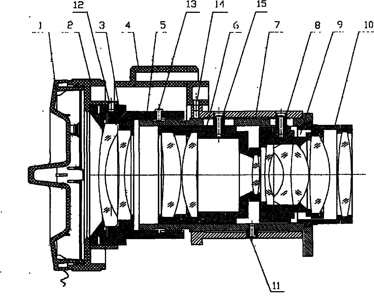
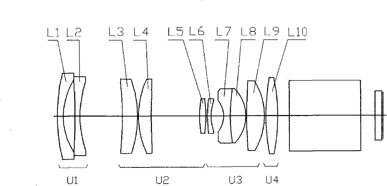
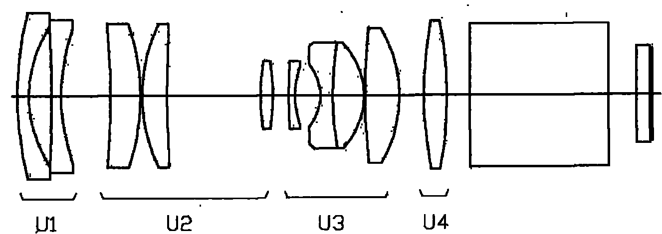
[0032] combine figure 1 , see figure 2 , image 3, the continuous zoom projection lens of the present invention, the main components include a lens cover 1, a focusing handwheel 2, a focusing lens barrel 3, a zooming handwheel 4, a guide barrel 5, a zoom lens barrel 6, a cam curve barrel 7, a roller guide Nail 8, compensation lens barrel 9, fixed lens barrel 10, roller guide nail 11, connecting screw 12, focus limit screw 13, connecting pin 14, roller guide nail 15 and optical system lens group. Among them: the focusing lens barrel 3 is connected to the front end of the guide tube 5 through threads, and the front part is set with a focusing hand wheel 2, and the two are connected together by a connecting screw 12, and the focusing ring 2 can be rotated to drive the focusing lens The cylinder 3 rotates accordingly, and moves axially relative to the guide cylinder 4 to realize the focusing function of the focusing group U1. In the position groove, the two ends of the limit g...


PUM


Abstract

The invention relates to a continuous zooming projection lens. An optical system lens group comprises a focusing group U1 with negative focal power, a focusing group U2 with positive focal power, a compensating group U3 with negative focal power and a back fixed group U4 with positive focal power, which are distributed along an optical axis in sequence from the screen side to the image plane side; the focusing is realized by the back-and-forth movement of the U1 group; the zooming is realized by the homodromous movement of the U2 and the U3 from the wide angle end to the remote shooting end along the optical axis; in the zooming process, the total distance from the first surface of a lens to the image plane is not changed; the projection lens has the characteristic of achieving satisfactory imaging quality on the image plane of a longer back working distance, and the like; and the lenses all adopts spherical lenses, has high manufacturability and is suitable for mass production.

Description

technical field [0001] The invention belongs to the technical field of digital projectors, and in particular relates to a continuous zoom projection lens used in conjunction with a TIR prism illumination light path, which is applied to a digital projector using DLP technology. Background technique [0002] With the development and deepening of semiconductor technology, digital projection display technology has been developed, and the projection display industry based on DLP, LCOS, LCD and other technologies has developed rapidly. In recent years, DLP projection display technology has developed rapidly with its rich colors, high-definition images, high-brightness images and high-contrast displays. It can achieve smaller and lighter product features, especially in cinemas. In the field of digital projection, its advantages are unparalleled. The core component of DLP technology mainly adopts DMD digital image chip. DMD is a digital image chip exclusively mastered and developed...

Claims


Application Information

Patent Timeline
Patent Type & Authority Applications(China)
IPC IPC(8): G02B15/177G02B1/00G02B3/00
Inventor 曹红曲赵武李跃甫李智超
Owner NANYANG LIDA PHOTOELECTRIC
Why Eureka
Try Eureka